Single Pulse Generation with the STM8S
Monday, September 3rd, 2012I have recently been looking at using a sensor which uses a one-wire communication protocol. The protocol uses a single pulse of a defined length to trigger the unit to send the sensor reading back down the same wire. This lead me on to thinking about how I could achieve this, the results of which are documented here.
Whilst the main purpose of the code we will be developing in this post remains the same, i.e. to produce a single pulse of a defined length, I felt it important to show the two fundamental ways in which this can be achieved:
- Interrupts and GPIO
- Timers
Much of the first method, using interrupts and GPIO signals is a relatively straight forward case of modifying one of the previous examples, namely Using Timers on the STM8S.
The second method is more interesting as we look at using Timers to solve this problem. This will start us looking at using Timer 1. This is probably the most flexible and powerful of the Timers on the STM8S. This power and flexibility comes with a price, it is also the most complex of the timers we have at our disposal.
As an aside, we will look at measuring the length of the pulses we can generate with the aim of defining the minimum pulse length we can create using each of the methods.
So let’s start with a common problem definition. We will use both methods to generate a single pulse lasting 30 uS.
Method 1 – Interrupts and GPIO
This method requires only slight modifications to the code presented in Using Timers on the STM8S. So let’s start by downloading the example and modifying the code.
The first thing we will need to do is to modify the duration of the timer in order to generate and interrupt every 30 uS. In the original program we setup Timer 2 as follows:
//
//  Setup Timer 2 to generate a 20 Hz interrupt based upon a 16 MHz timer.
//
void SetupTimer2()
{
    TIM2_PSCR = 0x03;       //  Prescaler = 8.
    TIM2_ARRH = 0xc3;       //  High byte of 50,000.
    TIM2_ARRL = 0x50;       //  Low byte of 50,000.
    TIM2_IER_UIE = 1;       //  Enable the update interrupts.
    TIM2_CR1_CEN = 1;       //  Finally enable the timer.
}
From the previous article we know that the following formula applies:
(2TIM2_PSCR * counter) = fmaster / finterrupt
Now we are looking at generating a high frequency (low duration) pulse and so it is not unreasonable to set the prescalar to 1 (i.e. TIM2_PSCR = 0). This simplifies the formula to:
counter = fmaster / finterrupt
We also know that finterrupt is given by the following formula:
finterrupt = 1 / pulse duration
Putting the two together gives:
counter = fmaster * pulse duration
counter = 16,000,000 * 30 * 10-6
counter = 480 (0x1e0)
So our code becomes:
//
//  Setup Timer 2 to generate an interrupt every 480 clock ticks (30 uS).
//
void SetupTimer2()
{
    TIM2_PSCR = 0x00;       //  Prescaler = 1.
    TIM2_ARRH = 0x01;       //  High byte of 480.
    TIM2_ARRL = 0xe0;       //  Low byte of 480.
    TIM2_IER_UIE = 1;       //  Turn on the interrupts.
    TIM2_CR1_CEN = 1;       //  Finally enable the timer.
}
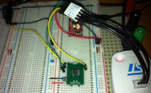
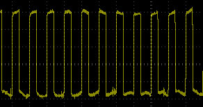
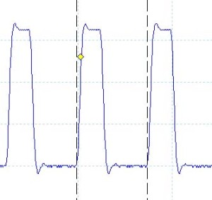
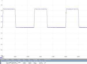
If you hook up oscilloscope and deploy the code you should find that the STM8S is generating square wave on Post D, Pin 5. The frequency of the signal should be 60 uS (see the previous article for an explanation where this comes from) with a duty cycle of 50%. Each of the components should have a width of 30 uS.
The next thing we need to do is to make the system generate a single pulse instead of a square wave. The solution is shockingly simple; in this case we turn off the timer interrupt after the first pulse has been generated.
The code in the Interrupt Service Routine (ISR) currently looks like this:
//
//  Timer 2 Overflow handler.
//
#pragma vector = TIM2_OVR_UIF_vector
__interrupt void TIM2_UPD_OVF_IRQHandler(void)
{
    PD_ODR_ODR4 = !PD_ODR_ODR4;     //  Toggle Port D, pin 4.
    TIM2_SR1_UIF = 0;               //  Reset the interrupt otherwise it will fire again straight away.
}
When we initialise the GPIO port we start with the output set to low. The timer interrupt code then toggles the GPIO port. So the first time this ISR is called the GPIO port goes high, the second time the GPIO port goes low etc. This means we need to turn off the interrupt when we transition from high to low for the first time. This results in the following code:
//
//  Timer 2 Overflow handler.
//
#pragma vector = TIM2_OVR_UIF_vector
__interrupt void TIM2_UPD_OVF_IRQHandler(void)
{
    unsigned char data;

    data = PD_ODR_ODR4;
    PD_ODR_ODR4 = !data;            //  Toggle Port D, pin 5.
    if (data == 1)
    {
        TIM2_IER_UIE = 0;           //  Only allow the pulse to happen once.
    }
    TIM2_SR1_UIF = 0;               //  Reset the interrupt otherwise it will fire again straight away.
}
This method turns off the Timer 2 interrupt and only the Timer 2 interrupt but resetting the interrupt enable flag for Timer 2 (TIM2_IER_UIE = 0). We could have called __disable_interrupt() here but this would have turned off all interrupts.
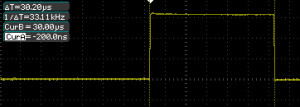
Deploying this code results in the following output on the oscilloscope:
And just to prove that the application generated a single pulse I hooked up the logic analyser and set this up to capture over 10 seconds worth of data. This resulted in the following output:
As you can see, we have what looks like a single pulse (see the logic analyser output). Zooming in on the pulse on the logic analyser output confirmed that there is indeed only a single pulse. A quick check of the oscilloscope output confirmed that the duration of the pulse is 30 uS.
Method 2 – Timers and PWM
In Generating PWM Signals using the STM8S we saw how we can generate a PWM signal without having to use interrupts. Here we will extend the principle to generating a single pulse using the One Pulse Mode (OPM) feature of Timer 1 (note that OPM is not available on Timer 2). As with the above, we will do this is two stages, namely to generate a PWM signal and then to restrict the output to a single pulse.
So let’s start by looking at Timer 1 and what we will need for this example.
TIM1_ARRH & TIM1_ARRL – Timer 1 Auto Reload Registers
As with Timer 2, these are two 8-bit registers which when combined make up the 16-bit counter value. To reset the 16-bit value we need to write to TIM1_ARRH before writing to TIM_ARRL as writing to TIM1_ARRL triggers the update of the registers.
TIM1_PSCRH & TIM1_PSCRL – Timer 1 Prescalar
This is a 16-bit register and allows finer control over the prescalar than we had with Timer 2. In this case the value can be any value from 0 to 65535. The frequency of the counter (fcounter) is given by the following frequency:
fcounter = fmaster / (Prescalar + 1)
This means that the range of the divisor used is actually 1 to 65536.
As with the auto-reload register, we should load the high bits before the low bits (i.e. TIM1_PSCRH before TIM1_PSCRL).
TIM1_RCR – Timer 1 Repetition Counter
The repetition counter allows for the timer to generate update events only when a number of repetitions of the counter underflow and overflow have occurred. This is a topic which is outside of the scope of this example and so we will set this to 0 for the moment and return to this topic in future examples.
TIM1_CR1 – Timer 1 Control Register 1
We will be ensuring that two bits in this register are set; namely TIM1_CR1_DIR and TIM1_CR1_CMS.
TIM1_CR1_DIR controls the direction of the counter as counter 1 can count from 0 upwards or from TIM_ARR down to 0. Setting this value to 0 means count upwards whilst 1 means count downwards.
TIM1_CR1_CMS determines the counter alignment. For this example we will be using edge aligned counting and will be setting this to 0. Note that this value is a two bit value and the meaning of the remaining values is left for a future discussion.
TIM1_CCRM4 – Timer 1 Capture/Compare Mode Register 4
As with Timer 2, we can control the PWM mode setting this to either mode 1 or mode 2. We will configure this channel to be operating in PWM mode 2. In this mode OC3 will be inactive as long as the counter < TIM1_CCR3.
TIM1_CCR4H & TIM1_CCR4L – Timer 1 Capture Compare Register 4
These registers together form a 16-bit value for use in Capture/Compare/PWM mode. In PWM mode, these values coupled with the TIM1_ARR registers will allow control of the duty cycle of a PWM signal.
TIM1_CCER2 – Timer 1 Capture/Compare Register 2
This register determines the output polarity and availability of Timer 1, channel 4 (amongst other things). The bits we are really interested in are the availability and the polarity of the output.
TIM1_CCER2_CC4E determines if the output is enabled or disabled; 0 is disabled, 1 is enabled.
TIM2_CCER2_CC4P determines the polarity of the active stage of the output. A polarity of 0 means that the active stage gives a high (logic 1) output, whilst a polarity of 1 gives a low (logic 0) output.
Software
So if we put all of this together we get an application which looks something like this:
//
//  This program shows how you can generate a single pulse using
//  timers on the STM8S microcontroller.
//
//  This software is provided under the CC BY-SA 3.0 licence.  A
//  copy of this licence can be found at:
//
//  http://creativecommons.org/licenses/by-sa/3.0/legalcode
//
#if defined DISCOVERY
    #include <iostm8S105c6.h>
#elif defined PROTOMODULE
    #include <iostm8s103k3.h>
#else
    #include <iostm8s103f3.h>
#endif
#include <intrinsics.h>

//
//  Setup the system clock to run at 16MHz using the internal oscillator.
//
void InitialiseSystemClock()
{
    CLK_ICKR = 0;                       //  Reset the Internal Clock Register.
    CLK_ICKR_HSIEN = 1;                 //  Enable the HSI.
    CLK_ECKR = 0;                       //  Disable the external clock.
    while (CLK_ICKR_HSIRDY == 0);       //  Wait for the HSI to be ready for use.
    CLK_CKDIVR = 0;                     //  Ensure the clocks are running at full speed.
    CLK_PCKENR1 = 0xff;                 //  Enable all peripheral clocks.
    CLK_PCKENR2 = 0xff;                 //  Ditto.
    CLK_CCOR = 0;                       //  Turn off CCO.
    CLK_HSITRIMR = 0;                   //  Turn off any HSIU trimming.
    CLK_SWIMCCR = 0;                    //  Set SWIM to run at clock / 2.
    CLK_SWR = 0xe1;                     //  Use HSI as the clock source.
    CLK_SWCR = 0;                       //  Reset the clock switch control register.
    CLK_SWCR_SWEN = 1;                  //  Enable switching.
    while (CLK_SWCR_SWBSY != 0);        //  Pause while the clock switch is busy.
}

//
//  Set up Timer 1, channel 4 to output a single pulse lasting 30 uS.
//
void SetupTimer1()
{
    TIM1_ARRH = 0x03;       //  Reload counter = 960
    TIM1_ARRL = 0xc0;
    TIM1_PSCRH = 0;         //  Prescalar = 0 (i.e. 1)
    TIM1_PSCRL = 0;
    TIM1_CR1_DIR = 0;       //  Up counter.
    TIM1_CR1_CMS = 0;       //  Edge aligned counter.
    TIM1_RCR = 0;           //  No repetition.
    //
    //  Now configure Timer 1, channel 4.
    //
    TIM1_CCMR4_OC4M = 7;    //  Set up to use PWM mode 2.
    TIM1_CCER2_CC4E = 1;    //  Output is enabled.
    TIM1_CCER2_CC4P = 0;    //  Active is defined as high.
    TIM1_CCR4H = 0x01;      //  480 = 50% duty cycle (based on TIM1_ARR).
    TIM1_CCR4L = 0xe0;
    TIM1_BKR_MOE = 1;       //  Enable the main output.
	//
	//	Uncomment the following line to produce a single pulse.
	//
//    TIM1_CR1_OPM = 1;
    TIM1_CR1_CEN = 1;
}

//
//  Main program loop.
//
void main()
{
    //
    //  Initialise the system.
    //
    __disable_interrupt();
    InitialiseSystemClock();
    SetupTimer1();
    __enable_interrupt();
    while (1)
    {
        __wait_for_interrupt();
    }
}
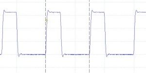
If we run this application and hook up the oscilloscope to Timer 1, channel 4 (Pin 13 on the STM8S103F3 TSSOP20 package) we should find we get a PWM signal with a 60 uS period and a 50% duty cycle.
Timers and One Pulse Mode
Now that we have PWM functioning as expected we really only have to make one minor code modification, namely to set the timer generating a single pulse. For this we only need to add one line of code to the above application, SetupTimer1 becomes:
//
//  Set up Timer 1, channel 4 to output a single pulse lasting 30 uS.
//
void SetupTimer1()
{
    TIM1_ARRH = 0x03;       //  Reload counter = 960
    TIM1_ARRL = 0xc0;
    TIM1_PSCRH = 0;         //  Prescalar = 0 (i.e. 1)
    TIM1_PSCRL = 0;
    TIM1_CR1_DIR = 0;       //  Up counter.
    TIM1_CR1_CMS = 0;       //  Edge aligned counter.
    TIM1_RCR = 0;           //  No repetition.
    //
    //  Now configure Timer 1, channel 4.
    //
    TIM1_CCMR3_OC3M = 7;    //  Set up to use PWM mode 2.
    TIM1_CCER2_CC3E = 1;    //  Output is enabled.
    TIM1_CCER2_CC3P = 1;    //  Active is defined as high.
    TIM1_CCR3H = 0x01;      //  480 = 50% duty cycle (based on TIM1_ARR).
    TIM1_CCR3L = 0xe0;
    TIM1_BKR_MOE = 1;       //  Enable the main output.
    TIM1_CR1_OPM = 1;		//	Enable single pulse mode.
    TIM1_CR1_CEN = 1;
}
How Fast Can We Go?
Each of the above programs has their limitations. Assuming the same clock speed, the interrupt method is restricted by the number of instructions which must be executed in order to toggle the GPIO pin and work out if this is the first or seconded invocation of the ISR. The second is really only restricted by the speed of the system clock. This does not mean we cannot experiment to determine which is faster.
In both cases the programs were modified changing the timer auto-reload registers and the capture compare registers. The auto-reload register was always set to a value twice that of the capture compare register. For the interrupt method the fastest pulse which could be achieved was in the order of 2.5 uS (ARR = 0x0004) whilst the OPM method resulted in a pulse width of 146 nS (TIM1_ARR = 0x0002).
Conclusion
In this article we have looked at two methods which we can use to generate a single pulse. I am not offering advice on which is better, I’ll leave this to you as the application developer to decide.
Hopefully you will have gained an appreciation of the power of Timer 1. You should also have realised that using Timer 1 is not as simple as using Timer 2. There are a number of features we have not touched upon including (but not restricted to):
- Capture/Compare
- PWM Modes
- Timer synchronisation
I am sure that we shall return to Timer 1 in future posts.
As always, the source code is available for download.
Source Code Compatibility
| System | Compatible? |
| STM8S103F3 (Breadboard) | |
| Variable Lab Protomodule | |
| STM8S Discovery |
