Komodex Seven Segment Display and Breakout Modules
Komodex Labs recently released a couple of new modules for the Netduino GO! platform. The first is a seven segment display module and as we will see later this can be used to show sensor data. The second module is a breakout module for the GO! bus and this is probably more interesting to module developers.
As the postman was kind to me and managed to get these modules to me this week I thought I’d hook them up to the light sensor I have been playing with to see what they can do.
A Little Background
I have recently been working with a simple sensor to teach myself how to work with the STM8S. It has been a long slow task as the normal competing pressures of work, the house and general life stuff keeps calling for my attention.
The project uses a TSL235R sensor which converts the current ambient light level into a square wave with 50% duty cycle. The STM8S periodically reads the frequency of the signal generated by the sensor. This value is then made available to the Netduino GO! via the GO! Bus.
This project is going to read the value from the STM8S and display it on the seven segment display. The value is a 16-bit value and so can range from 0 to 65535 so we will be showing the value in hex.
Seven Segment Module
The seven segment display is a nice little module very professionally finished. It feels a solid – sort of odd to say that about a module. I was kind of surprised by the weight but then I have only been working with small modules so far.
I’d write more but I think the module is best described my Matt’s blog post. This shows some photos of the module along with a description of the API used to control it.
GO! Bus Breakout Module
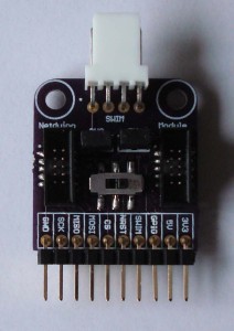
This is a handy little module which only had a short production run. I was lucky enough to have ordered one before stock ran out. The module is aimed at module developers. It has a couple of sockets for module cables along with some handy breakout points.
The idea is simple, you connect your Netduino GO! to one side of the breakout board and your module to the other side of the breakout board. You can then hook up test equipment (scope / logic analyser etc.) to a row of headers on the board. This allows you to debug your module by snooping on the data going down the GO! Bus.
An alternative configuration and one I am using for development on breadboard, is to connect the breakout module to breadboard with the Netduino GO! connected to one side of the breakout board. This allows you to feed the GO! Bus signals into your circuit whilst at the prototype stage.
The breakout also has a lovely feature in that you can connect the ST-LInk/V2 module to the board and at the flick of a switch you can disconnect the SWIM/NRST signals from the Netduino GO! and connect them to the ST-Link/V2 instead. This allows you to re-program the STM8S on the fly without having to modify your circuit – NEAT !
For more information about this module I’d head over to Matt’s blog post.
Hooking it all up
Connecting the Seven Digit Module up to the go was easy, it simply needed a standard 5cm GO! Bus cable and that’s it.
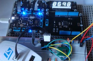
The Breakout module was a little more difficult as it had to be hooked into an existing prototype circuit. From the Netduino side it was easy, just another 5cm GO! Bus cable. The ST-Link/V2 connection was also easy as the module has a connector already on the board and it is designed to ensure that the connection can only be made one way. The only complication was then ensuring that the connections between the GO! Bus and the prototype circuit were correct. Adding this module has in fact made my prototype circuit a little cleaner.
Here’s what the final circuit looks like:
Installing the Drivers
The Seven Segment Module is supplied with a set of drivers in the form of an executable. The drivers can be found on the Komodex Labs web site. Installation was quick, simple and painless.
Komodex Labs also provide the source code for the drivers along with a sample application. This is a separate download and as you will see later, this came in handy.
As you would expect, the breakout module does not require any drivers as there is no interaction between the module and the PC.
Writing the Software
The API provided with the module is comprehensive but in this case we are going to use only a small part of it. We need to display a hex representation of a 16-bit number.
So the first step is to create a new project and add a reference to the module. You will have to browse to the directory in which you installed the drivers and add the Komodex.NETMF.SevenSegmentDisplay.dll file. On my machine this was installed in C:Program Files (x86)KomodexModule DriversAssembliesv4.2
The next step is to add a using statement
using Komodex.NETMF;
and then declare and instantiate an instance of the module:
SevenSegmentDisplay display = new SevenSegmentDisplay();
display.SetValue(0);
The above shows the module being instantiated and the display value set to 0.
The remainder of the program continuously polls the sensor for a reading. This reading is converted into a string containing the hexadecimal representation of the reading. This reading is then displayed on the Seven Segment Module. The code looks something like this:
while (true)
{
	short diff = module.GetReading();
	string output = "";
	char c;
	for (int index = 3; index >= 0; index--)
	{
		int nibble = (diff >> (4 * index)) & 0xF;
		if (nibble < 10)
		{
			output += nibble.ToString();
		}
		else
		{
			c = (char) ('A' + nibble - 10);
			output += c.ToString();
		}
	}
	display.SetValue(output);
	Thread.Sleep(1000);
}
The line short diff = module.GetReading(); obtains a reading from the sensor module which I am prototyping. This value could come from any sensor or from any source / calculation.
Hitting F5 deployed the code to the Netduino GO! and values quickly started appearing on the display. Success!
No… Wait…
I’m getting some unexpected output. Every now and then the module displays a number with some spaces in place of digits. Hmmmmm… what is going on!
Time for a quick test program. I know that the module works OK as the test projects ran fine. Adding a Debug.Print of the output variable gave me a clue. There was a pattern. Any numbers with the digit 9 in them showed a space instead of a digit. A quick test program showed that displaying 2929 where the variable of type int displayed the number correctly. Doing the same where the value was stored in a string showed any digit except the digit 9, these were replaced with spaces. Now we know where the problem is.
As noted earlier, Komodex Labs supply the source code for the drivers. So opening this project and some poking around the code for the display resulted in the problem being found. A quick modification to the source, recompile and then reference the newly compiled DLL in my code and Success !
Edit: Komodex labs have confirmed that the driver has been patched and as of 27/07/2012 the driver download contains the fix for the problem noted.
Here is a short video of the sensor and display working together:
Tags: Electronics, Netduino
Friday, July 27th, 2012 at 6:00 am • Electronics, Netduino • RSS 2.0 feed Both comments and pings are currently closed.


