Threaded Inserts and 3D Printed Mounts
Saturday, April 1st, 2023
Threaded insert in pillar
Way back in 2019, Hackaday posted an article on Threading 3D Printed Parts: How to Use Heat-set Inserts which discussed how to use brass inserts in 3D printed parts to make connecting parts easier and more robust. The article presented the changes you should make to prints in order to make adding the inserts easier to locate and some of the tools that could be purchased to make using these inserts easier.
I have been using these type of inserts for a few years now and this month came up with a slight variation on the method discussed in the above article. The process of laying out the part remains the same, the change made is to the method of fixing the brass threaded insert into the 3D printed part.
The original article discussed using special tools for heating the threaded insert and pushing the heated part into the 3D printed model. This article presents an alternative to a specialist part by using nothing more than some scrap protoboard. The beauty of this technique is that it does not require any special tools.
Requirement
I regularly use a number of different microcontroller development boards and debug probes for firmware development. These boards commonly have components on the bottom of the boards and / or through hole parts where the legs of the components protrude through the board and potentially damage desks / work surfaces.
A 3D printed mount or frame keeps any components away from work surfaces protecting them from scratches and also reduces the possibility of shorting components on the boards themselves.
The process will be illustrated with a Spresense board and external adapter.
The technique should meet the following requirements:
- Use tools that any maker should have in their workshop
- Present a flat surface around the insert
- Keeps tools clear of any melted material
3D Design
The external Spresense adapter board has four mounting holes and the intention is to use two of the holes to acts as locators and two holes to fix the board in place. The mount will have four pillars under the holes in the external adapter board. Two of these will have printed pins to act as locators. Two of the pillars will use threaded inserts to allow screws to fix the board in place. A picture is worth a thousand words so here is how the final design looks:
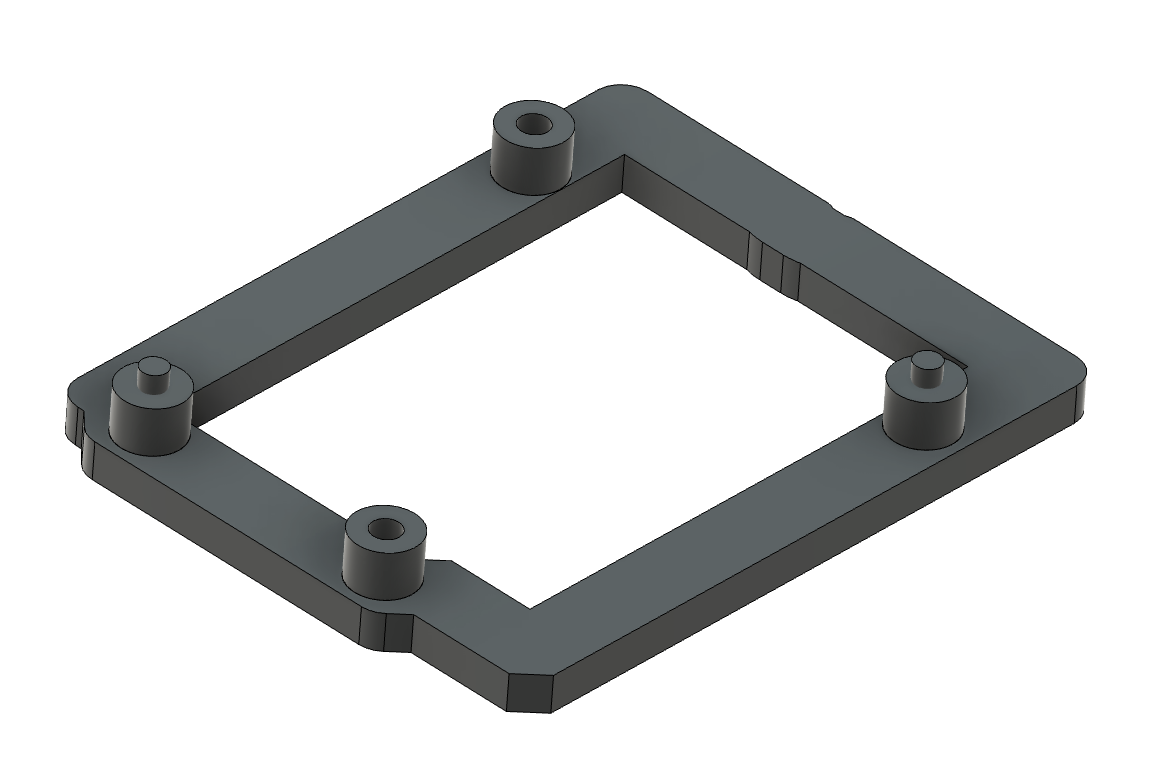
Fusion 360 design for Spresense mount
Adding the Threaded Insert
The starting point of the process is the 3D printed frame with the objective of embedding the threaded insert securely into the printed part. The pillar is a simple cylinder with a hole running through to the base of the frame.
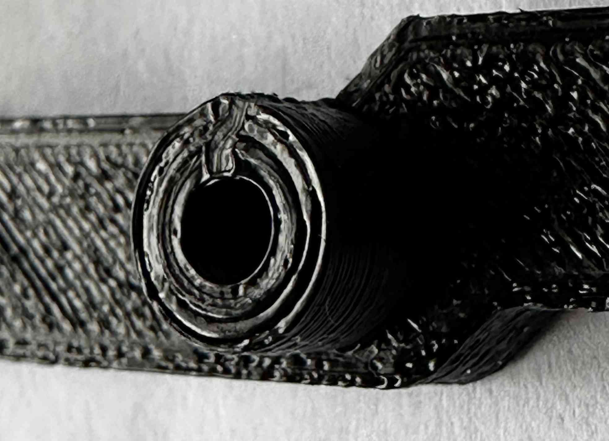
Pillar on mount
The first step is to prepare the threaded insert for insertion into the frame. This is done by using a screw matching the insert mating the two through a piece of protoboard:
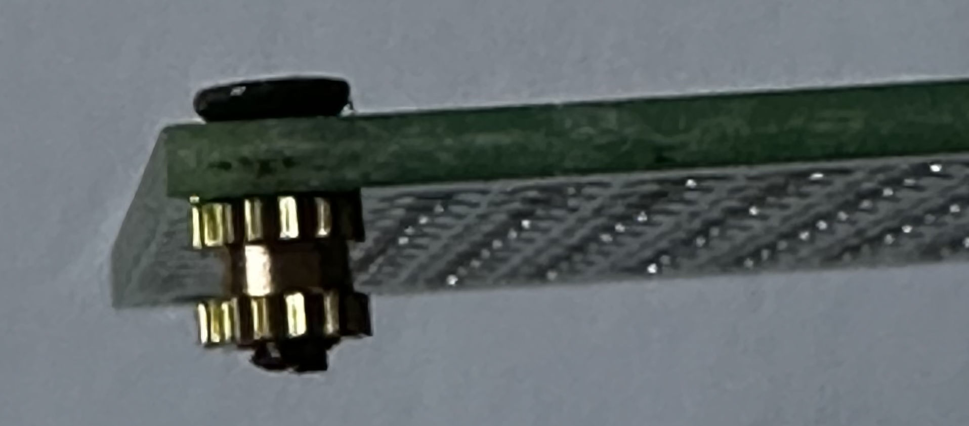
Threaded insert on protoboard
Next up, the insert in placed in the hole in the pillar and the protoboard is used to hold the insert in place. The tip of a hot soldering iron is placed on the head of the screw and a slight pressure is applied using the protoboard:
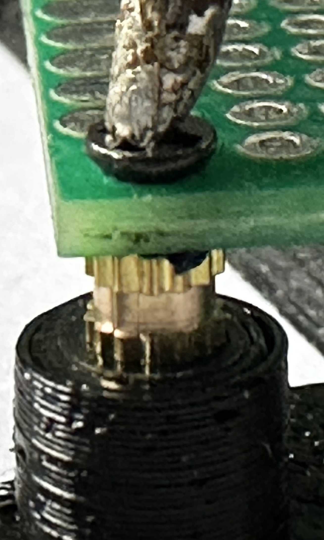
Adding threaded insert (stage 1)
Continue applying pressure using the protoboard as the part sinks into the 3D printed part:
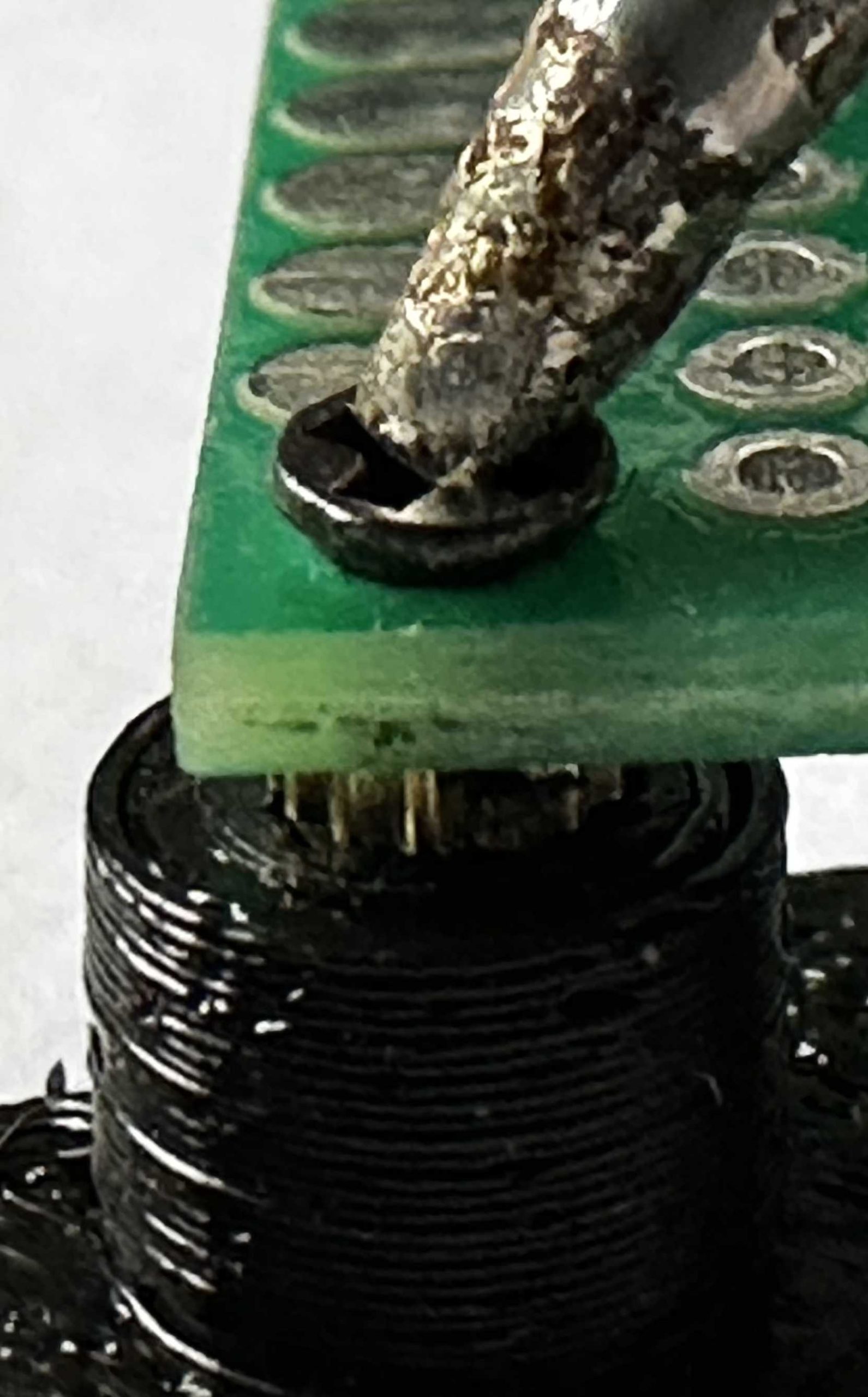
Adding threaded insert (stage 2)
By continuing to apply pressure, the protoboard will finally hit the top of the pillar. At which point remove the soldering iron and hold the protoboard in place for a few seconds. This will allow the PLA to set around the insert.
Adding threaded insert (stage 3)
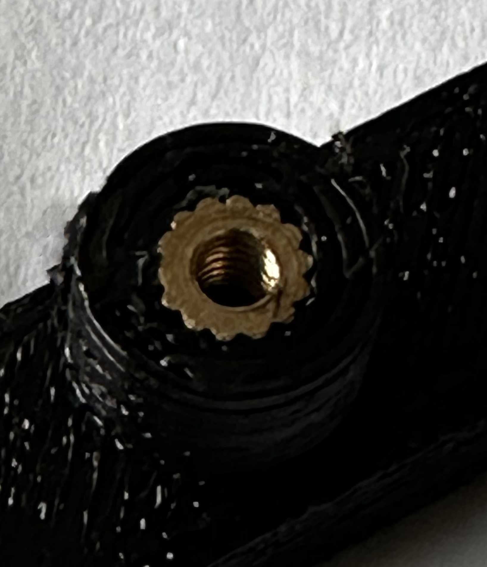
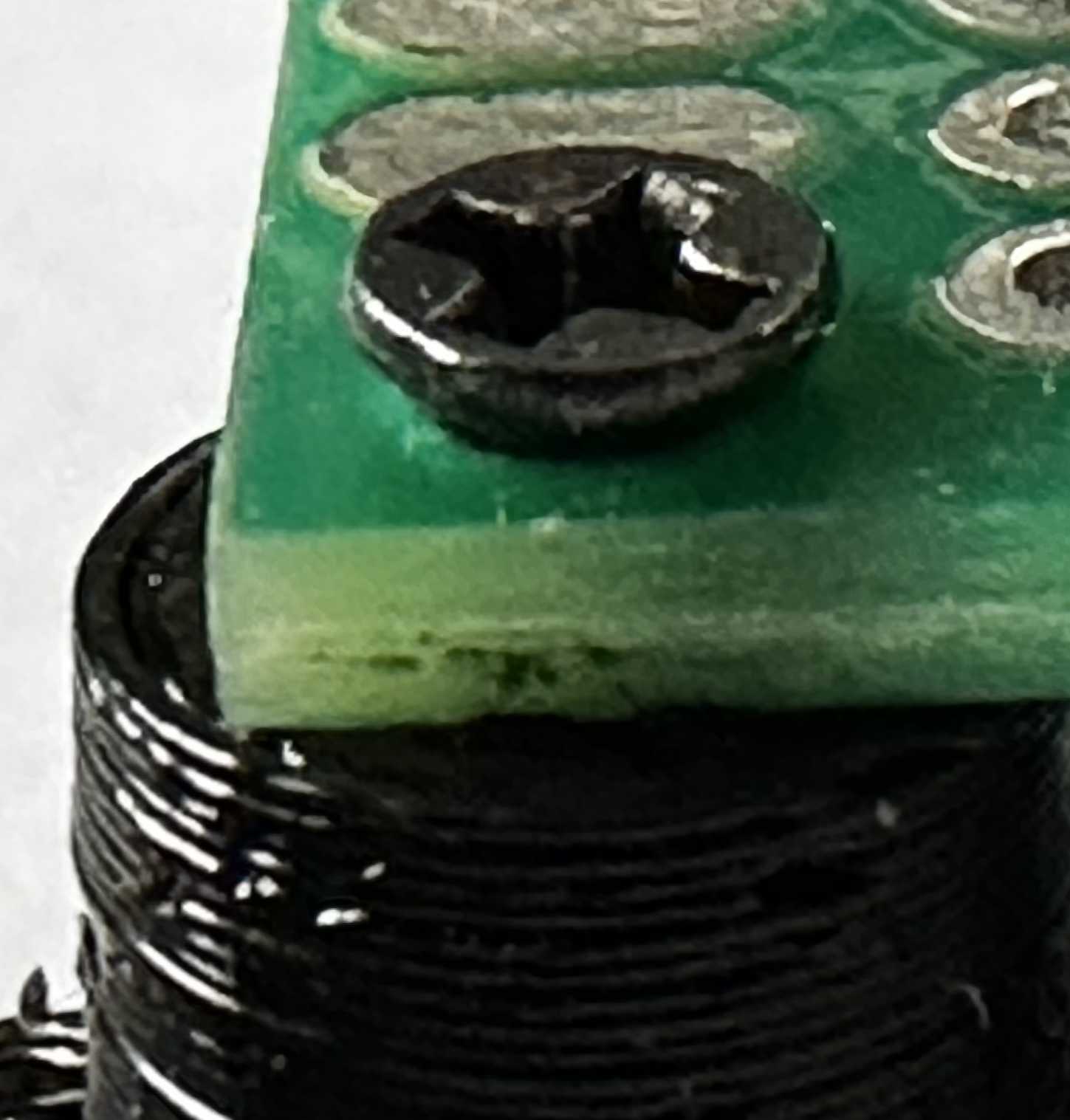
Finally, remove the screw from the board to reveal the insert which should now be firmly embedded into the pillar.

Threaded insert in pillar
Conclusion
The technique presented uses simple tools which are available in many makers workshops or are relatively cheap to purchase. It achieves the objectives set out earlier in this post as well as those in the original Hackaday article.
Finally, here is the assembled board and mount.
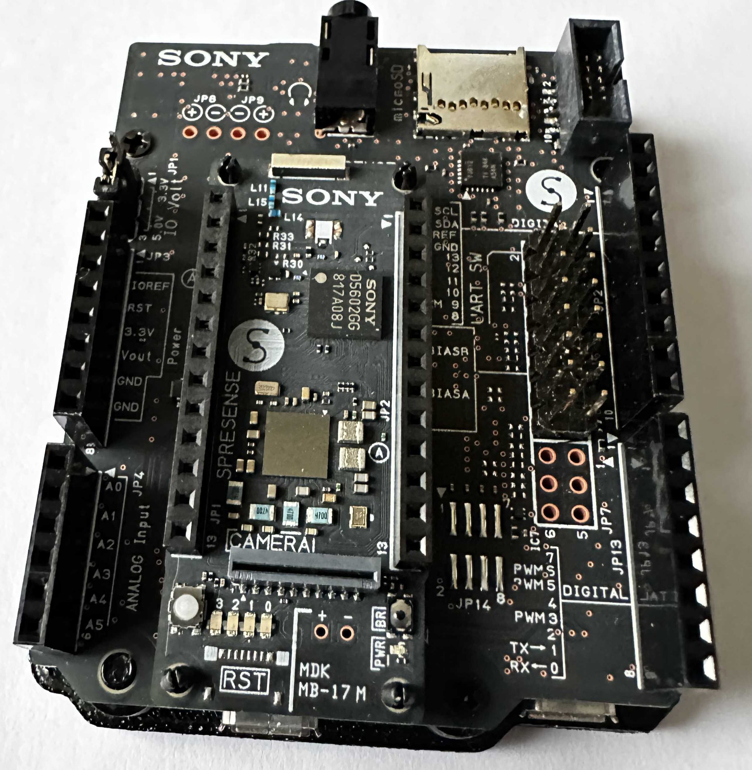
Spresense external carrier board on mount

