RSS

Archive for January, 2011

Don’t Panic Mr Mainwaring

Wednesday, January 26th, 2011

This evening saw a bit of a Dads Army moment. The Netduino would not talk to me or my laptop. There I sat with a brilliant idea for a new project and the little devil just looked at me. Had I killed the hardware with static?

Quick search of the Netduino forums found the solution:

  1. Start MFDeploy
  2. Hold down the push button on the Netduino and plug it into the computer
  3. Click on the Erase button in MFDeploy

A quick basic onboard LED program written, compiled and YES – deployed.

Phew… Now what was that brilliant idea again? Drat, so worried I forgot it.

And if you are interested, the original article can be found here.

An Expensive Thermometer

Sunday, January 16th, 2011

Whilst digging around the components I had ordered I found the digital temperature sensor break out boardI had ordered late last year. I feel a minor enhancement to the LCD project coming on.

Objective

Add the temperature sensor to the project and display the temperature on the LCD.

Hardware

Wiring up the additional hardware is relatively straight forward as we only need four additional connections. I was also helped greatly by Rick Winscot’s post on the Netduino forums. Rick’s post not only contained a class for the temperature sensor but also some helpful comments which gave the wiring to be used.

PinConnection
GND Ground
3.3V3.3V supply from the Netduino
SDAAnalog pin 4 on the Netduino
SCLAnalog pin 5 on the Netduino

Software

The software was a also simple given that Rick had already done all of the hardwork. It was a simple case of adding the class from Rick’s post to the project and modifying the main program loop to the following:

GpioLcdTransferProvider lcdProvider; 
Lcd lcd;  
lcdProvider = new GpioLcdTransferProvider(rs: Pins.GPIO_PIN_D12, enable: Pins.GPIO_PIN_D11, d4: Pins.GPIO_PIN_D2, d5: Pins.GPIO_PIN_D3, d6: Pins.GPIO_PIN_D4, d7: Pins.GPIO_PIN_D5); 
lcd = new Lcd(lcdProvider);
lcd.Begin(columns: 16, lines: 2); 
lcd.Write("Hello, world!");  
string temperature; TMP102 temperatureSensor; 
TimeSpan time;  
temperatureSensor = new TMP102(); 
temperature = temperatureSensor.GetTemperature(); 
while (true) 
{
    if (temperature != null)
   {
       time = Utility.GetMachineTime();
       lcd.SetCursorPosition(column: 0, row: 1);
       lcd.Write(temperature + "C " + time.Hours + " : " + time.Minutes + ":"; + time.Seconds + "   ");
    }  Thread.Sleep(1000);
    temperature = temperatureSensor.GetTemperature(); 
}

I did make one slight change to the TMP102 class. The GetTemperature method as originally posted returned “0” if there was a problem reading the temperature. 0oC is within the range of the sensor and so I decided to return null for an invalid reading.

Observations

When I first started the project I had some Debug.Print statements in the code and I was reading the temperature every 200 milliseconds. At this speed I seemed to be getting a few null values being returned. After taking these statements out and setting the timer to 1second I appear to be getting stable readings. The first version of the software yielded the following output:

Comparing the output with the digital output on the central heating thermostat gives a difference of about two degrees.

As for the title, well adding the component prices together gives a cost of approximately £80 for this project when there are perfectly good digital thermometers out there for about £10. But where’s the fun in that!

Credits

As already noted, this project was helped greatly by Rick Winscot’s posting on the Netduino forums – Thanks for donating the code to the community.

Getting Data Out – 16 x 2 LCD

Saturday, January 15th, 2011

This week I decided to move my attention to displaying data from the Netduino. Whilst you can use Debug.Print statements to display data on the PC it defeats the object o0f having a micro controller if you have to have it hooked up to a PC in order to see what it is doing. So I decided to purchase a 16 character by 2 line LCD display like the one found here– in fact this is the one I purchased.

Objective

Hook up theNetduinoto the LCD display and show a message to the user.

Hardware

The interface on the display uses 16 pins although it is not necessary to use all of them. The LCD is being driven by a HD44780 (or equivalent) chip and so there is plenty of examples of wiring/code to control this device. The pin usage is as follows:

LCD PinDescription
1Ground
2+5V
3Operating voltage for LCD (the contrast)
4RS (High for data, Low for instructions)
5R/W (High for read, Low for write)
6Chip enable
7DB0 – Data Bus line 0
8DB1 – Data Bus line 1
9DB2 – Data Bus line 2
10DB3 – Data Bus line 3
11DB4 – Data Bus line 4
12DB5 – Data Bus line 5
13DB6 – Data Bus line 6
14DB7 – Data Bus line 7
15Back light +ve
16Back light ground

A little bit of internet searching and I found a site discussing connecting this device to the Arduino to this type of device along with some code. After a little more searching I found this blog by Szymon Kobalczyk discussing interfacing these types of devices to the Netduino using shift registers. Interestingly, he has published a library on Codeplex (Micro Crystal Library) which allows the control of these devices by the Netduino. Sounded perfect.

Szymon’s blog post discusses the use of shift registers to control the LCD display. This makes it possible to reduce the number of outputs required in order to control the display. At the moment I am just concerned with displaying data. Optimisation of the number and type of ports will come later.

The following Fritzing diagram shows how the Netduino and the LCD are wired up:

The 10K potentiometer is used to control the contrast on the display. The wiring is as follows:

LCD PinDescriptionConnection
1GroundGround (taken from Netduino)
2+5V+5V (taken from Netduino)
3Operating voltage for LCDCentre pin of the 10K potentiometer
4RS (High for data, Low for instructions)Netduino digial pin 12
5R/W (High for read, Low for write)Ground
6Chip enableNetduino digital pin 11
7DB0 – Data Bus line 0
8DB1 – Data Bus line 1
9DB2 – Data Bus line 2
10DB3 – Data Bus line 3
11DB4 – Data Bus line 4Netduino digital pin 2
12DB5 – Data Bus line 5Netduino digital pin 3
13DB6 – Data Bus line 6Netduino digital pin 4
14DB7 – Data Bus line 7Netduino digital pin 5
15Back light +ve+5V
16Back light groundGround

Software

As previously mentioned, the main library for controlling this device can be found on Codplex. A little digging around in the examples gave me the code I needed to control the LCD. So leaving the examples behind I compiled the library into a DLL. Next step was to create a new project and add a reference to the DLL. I added the following code to the new project:

GpioLcdTransferProvider lcdProvider;
Lcd lcd;

lcdProvider = new GpioLcdTransferProvider(rs: Pins.GPIO_PIN_D12, enable: Pins.GPIO_PIN_D11, d4: Pins.GPIO_PIN_D2, d5: Pins.GPIO_PIN_D3, d6: Pins.GPIO_PIN_D4, d7: Pins.GPIO_PIN_D5);
lcd = new Lcd(lcdProvider);
lcd.Begin(columns: 16, lines: 2);
lcd.Write("Hello, world!");
while (true)
{
    lcd.SetCursorPosition(column: 0, row: 1);
    lcd.Write(Utility.GetMachineTime().ToString());
    Thread.Sleep(100);
}

Observations

For some reason, the initial run of the project did not function as expected. For a while I was sitting there looking at a blank display. Playing around with the potentiometer did not correct the problem. At some point I disconnected the backlight and again tried to change the contrast and a few dim letters appeared. A little more playing and I soon had a working display with the backlight working.

The image above shows the application running without the backlight connected. One further enhancement would be to use the transistor as a switch idea to allow the back light to be controlled from the software.

And the next step is to follow Szymon’s blog to reduce the number of pins required. But first a trip to Farnell’sweb site for some parts.

Netduino Controlling External LED

Monday, January 3rd, 2011

In this third and final post in this series I will finally connect the Netduino Plus to the external LED circuit I have been putting together over the past few days.

Objective

Use the push button on theNetduino Plusto toggle the state of the LED in the external LED circuit built here. The experiment should use software to change the state of the external LED.

Hardware Modifications

Much of the hard work (for me anyway as I’m a software engineer and not a hardware designer)hasalready been completed as the circuit in the previous post was designed to use a small current from a 3.3 V signal to turn a LED on or off. The only two changes to make are:

  1. Disconnect the base resistor R2 from the 3.3 V supply and connect to an appropriate digital output pin on theNetduino Plus.
  2. Couple the ground on the power supply on theNetduino Pluswith the ground on the external circuit.

Software

The software will have to provide the following functionality:

  1. Hold the current state of the LED
  2. Listen for the on board button being pressed and change the state of the LED.

Firstly, create a new project in Visual Studio using the Netduino Plus template (full instructions for installing the tools and templates can be found on the Netduino Plus web site. Make sure the project properties are set to deploy the application to the hardware over the USB port.

Next we need to declare some class level variables:

///
/// Determine if the LED is on (true) or off (false)
///
private static bool LEDState; 
///
/// Output port used to control the external LED circuit. 
///
private static OutputPort ExternalLED;
///
/// Button on the Netduino Plus.
///  
private static InterruptPort OnBoardButton;

Next, we need to initialise the variables. In this case I am using pin D7 to control the LED. So we set up the port and then make sure the LED is turned off to start with.

ExternalLED = new OutputPort(Pins.GPIO_PIN_D7, false); 
LEDState = false; 
ExternalLED.Write(LEDState);

The final part of our main program instantiates the button and wires up the event handler:

OnBoardButton = new InterruptPort(Pins.ONBOARD_SW1, false, Port.ResistorMode.Disabled, Port.InterruptMode.InterruptEdgeLevelLow); 
OnBoardButton.OnInterrupt += new NativeEventHandler(button_OnInterrupt); 
// 
//  Wait indefinetly. 
// 
Thread.Sleep(Timeout.Infinite);

The final bit of the puzzle is to write the logic for the interrupt handler:

private static void button_OnInterrupt(uint data1, uint data2, DateTime time) 
{
    LEDState = !LEDState;
    ExternalLED.Write(LEDState);
    if ((OnBoardButton.Interrupt == Port.InterruptMode.InterruptEdgeLevelLow) || (OnBoardButton.Interrupt == Port.InterruptMode.InterruptEdgeLevelHigh))
    {
        OnBoardButton.ClearInterrupt();     
    }
}

Connecting the hardware to the computer by USB and hit F5. Pressing the button on the Netduino Plus changes the state of the LED from off to on. Pressing the button again reverses this.

Observations

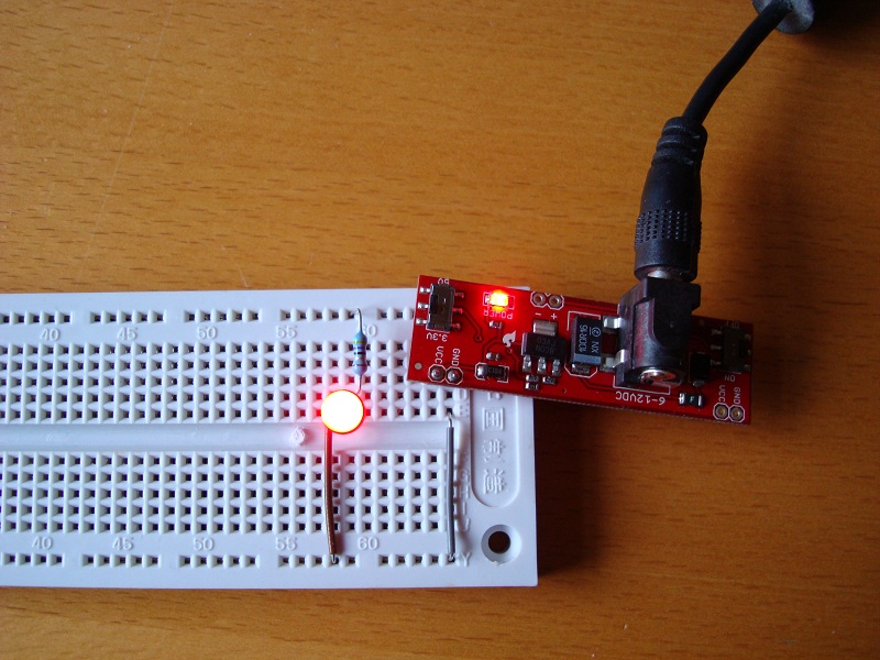
The final circuit looks like this:

One thing which did catch me out was the port interrupt mode settings. I started out setting the port (for the button) to InterruptEdgeLevelHigh and the system appeared to be generating an interrupt when the button was released. I pressed the button a few times and the state of the LED changed as I expected it to.

I decided it would be much more pleasing for the user if the LED state changed when the button was first pressed rather than having to wait for it to be released. So I changed the interrupt mode to InterruptEdgeLevelLow. Pressing the button did indeed change the state of the LED. However, subsequent presses of the button did not change the LED state.

Off to the .NET Microframework documentation, in particular the OnInterrupt event. Interestingly it notes the the ClearInterrupt method must be called if the input port is set to either InterruptEdgeLevelLow or InterruptEdgeLevelHigh. Interestingly in this application it was only required for one of these although the code above does call this method in both cases.

First project completed, I’m off to look for something more challenging.

C# Code for this project:NetduinoControllingExternalLED-Program.zip

Simple LED and Transistor Switch

Sunday, January 2nd, 2011

In my previous post I mentioned that I was working towards controlling a LED from the Netduino.  In fact the aim is to be able to control more than an LED but this is a start.  Step two is to use a transistor to control the LED by using the transistor as a switch.  By doing this I hope to be able to use this knowledge to control other devices which draw more current than the Netduino can supply (i.e. motors etc.).

Objective

The aim of this experiment is to control the circuit in the simple LED experiment using a transistor as a switch.  The LED should light when the input to the transistor is high and the LED should turn off when the input to the transistor is low.

The circuit should draw as little current as possible in order to switch the LED on in order that the switch can be used by the Netduino Plus.

Design

The circuit is a simple transistor circuit using the transistor as a switch.  In this case the transistor is either off or fully on (The voltage across the collector and emitter is almost zero and the transistor is saturated and cannot pass any more collector current).  The circuit design becomes something like this:

Note that the current limiting resistor for the LED circuit has been change to 100 ohms (as opposed to 47 ohms in the previous post).

The resistor R2 is used to drive the transistor. By breaking the connection we turn the transistor off and hence turn the LED off.  By restoring the connection we turn the transistor back on and hence turn the LED on.  The value of R2 has been chosen to provide a very small current to the base of the transistor.

Current to base of the transistor = V / R (from ohms law)
  = 3.3V / 2200 ohms
  = 1.5 mA

This falls well below the maximum current of 8 mA per pin provided by the Netduino Plus.

So we now have the limited current to trigger the switch and then only thing remaining is to work out which transistor to use.  For this I used The Electronics Club pages regarding transistors.  By following their calculations regarding choosing a suitable NPN transistor we get the following:

Load current on the collector = Supply voltage / Load resistance
  = 19 mA (modified from the last post)

The transistors minimum current gain (hFE) should be at least five times the current being driven through the load (Ic) divided by the maximum output from the chip driving the switch (i.e. from the Netduino Plus).

hFE(min) = 5 * (load current Ic / maximum current from the chip driving the circuit)
  = 5 * (26 mA / 8 mA)
  = 16.25 (minimum value)

On this basis the BC108 transistor was chosen as the hFE and the Ic values fall well within those calculated.  For the BC108:

IC 100 mA
hFE 110

The next step is to calculate the value for the resistor placed between the base of the transistor and the switching current.

RB = (Vc * hFE) / (5 * Ic)
  = (3.3V * 100) / (5 * 19mA)
  = 3473 ohms

The value for RB was set to 3k3 ohms.

Putting It All Together

The circuit was assembled using the values in the diagram above.  By connecting the base of the transistor to the 3.3V line through the 2K2 LED turned the LED on, disconnecting the resistor turned the LED off:

And so some measurements:

Measurement Value
Voltage drop across R1 1.34 V
Voltage drop across LED 1.86 V
Voltage drop across R2 2.52 V
Current through R2 0.5 mA

The next stage of the project is to connect this to the Netduino Plus and use this to turn the LED on / off preferably without burning it out :).

Simple LED Circuit

Saturday, January 1st, 2011

I suppose every journey starts with a single step, and often a small step at that.  Relearning the skills of yesteryear will be no different.  I’m slowly working myself up to controlling the LED from the Netduino Plus.  On this basis I’ll be taking it steady and tackle this in three parts:

  1. Light a LED from a 3.3V power supply
  2. Use a transistor as a switch to control the LED circuit above (more here)
  3. Use the Netduino Plus to control the transistor/LED circuit

The reason for taking this slowly is the Netduino Plus can only supply a small amount of current and I’m taking care to draw as little current as possible whilst still having a usable project.

So step one, a simple LED circuit from a static power supply

The design is simple (I’m not taxing myself too much) and requires little more knowledge that that provided by the LED data sheet and Ohms Law.  The task is to use a stable 3.3V power supply and use this to light up a red LED.  Minor complication here, I don’t have the datasheet for the LED so I’m not sure how much current it will take.  A quick search on Google provides a whole list of web sites with information on LEDs and the consensus of opinion is that modern red LEDs draw about 20mA max and have a typical voltage drop of around 2.5V (along with one comment that burning LEDs make a rather unpleasant smell).

Note 8 Jan 2011: Finally found the data sheet for the red LED being used and Vf = 2.5V and If = 20 mA.

Armed with this information I need to include a series resistor in the circuit to take the additional voltage drop and limit the current.

And for the calculations:

Voltage drop across the resistor = supply voltage – 2.5
  = 3.3 – 2.5 V
  = 0.8 V

Working on the resistor we get the following:

V = I * R
R = V / R
  = 0.8 V / 20 mA
  = 40 ohms

Now this resistor is not available as a standard component.  The nearest ones are 39 ohms and 43 ohms.  A quick look through my supply and I’ve got 33 ohms and 47 ohms.  So I plump for the 47 ohms and the circuit becomes:

The power supply itself will come from a breadboard power supply stick from Cool Components.

Theory over, now for the application

First job is to solder a couple of male header row connectors to the power supply to make it easier to connect to the power supply to the breadboard.  Next add the resistor and the LED and plug it all in.

The good news is it didn’t go bang and no hint of the smell of burning LEDs.  In fact it worked, one glowing red LED.

Simple LED Working

A quick check with the multi-meter revealed that

  1. The power supply is in fact delivering 3.25V and not the rated 3.3V.
  2. The voltage drop over the series resistor was 1.25V which means the circuit is drawing 26mA and the voltage drop across the LED is in fact only 2V.

All in all a small and simple first step.