Repeatable Deployments (Part 1)
Tuesday, March 19th, 2024

A common problem in the IT world is to create a consistent environment in a repeatable manner. This is important in a number of use cases:
- Development
- Testing
- Training
This series of posts will investigate using Ansible to create a consistent test environment, one that can be setup and torn down quickly and easily.
The starting point is setting up the hardware and installing the operating system (OS) which will be covered here. Subsequent posts will use Ansible to configure the system and deploy additional tools.
The Hardware
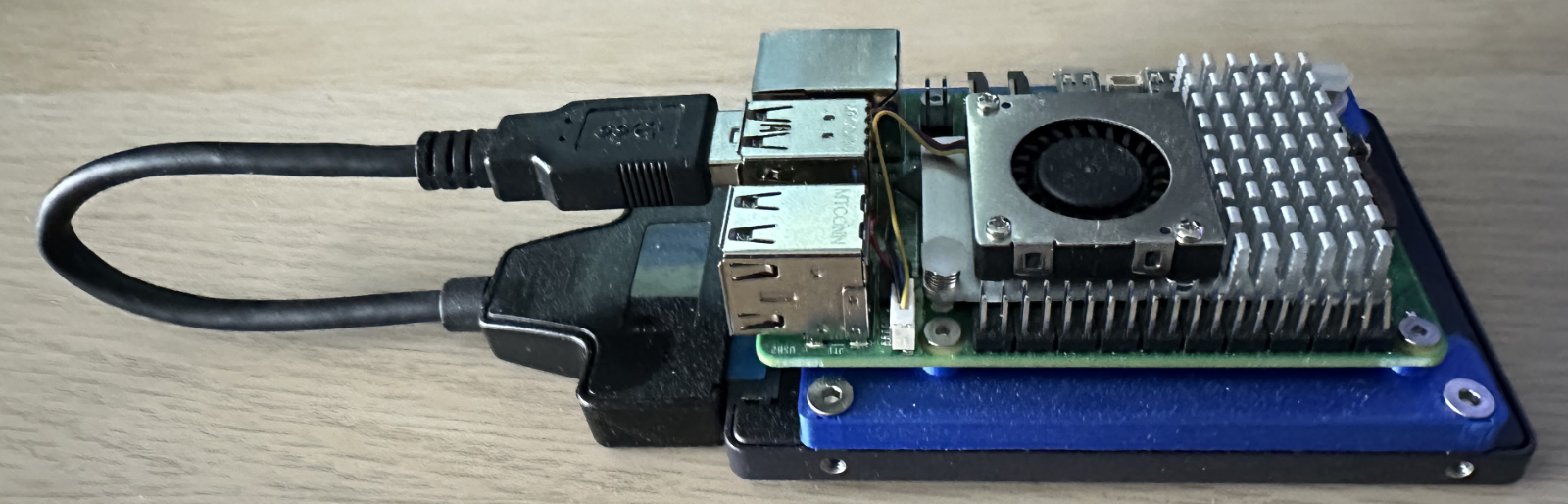
The test environment will be based around the Raspberry Pi 5 (although any version of the Pi hardware could be used). The system will be built around the following components:
- Raspberry Pi (3, 4 or 5)
- 256 GByte SATA SSD
- SATA to USB adapter
- Cooling fan (for the Raspberry Pi 5)
- Power Supply
- Ethernet cable
- 3D printed mounts to bring everything together
Grabbing a Raspberry Pi 5 and putting all of this together yields something like this:
Raspberry Pi Setup
SATA SSDs have been chosen for the OS and data storage as they are both faster and more reliable than SD cards. From a cost perspective they are not too much more expensive than a quality SD card. It should be noted that recent third party addon boards are becoming available that add one or two NVMe drives to be added to the the Raspberry Pi 5 using the PCIe bus.
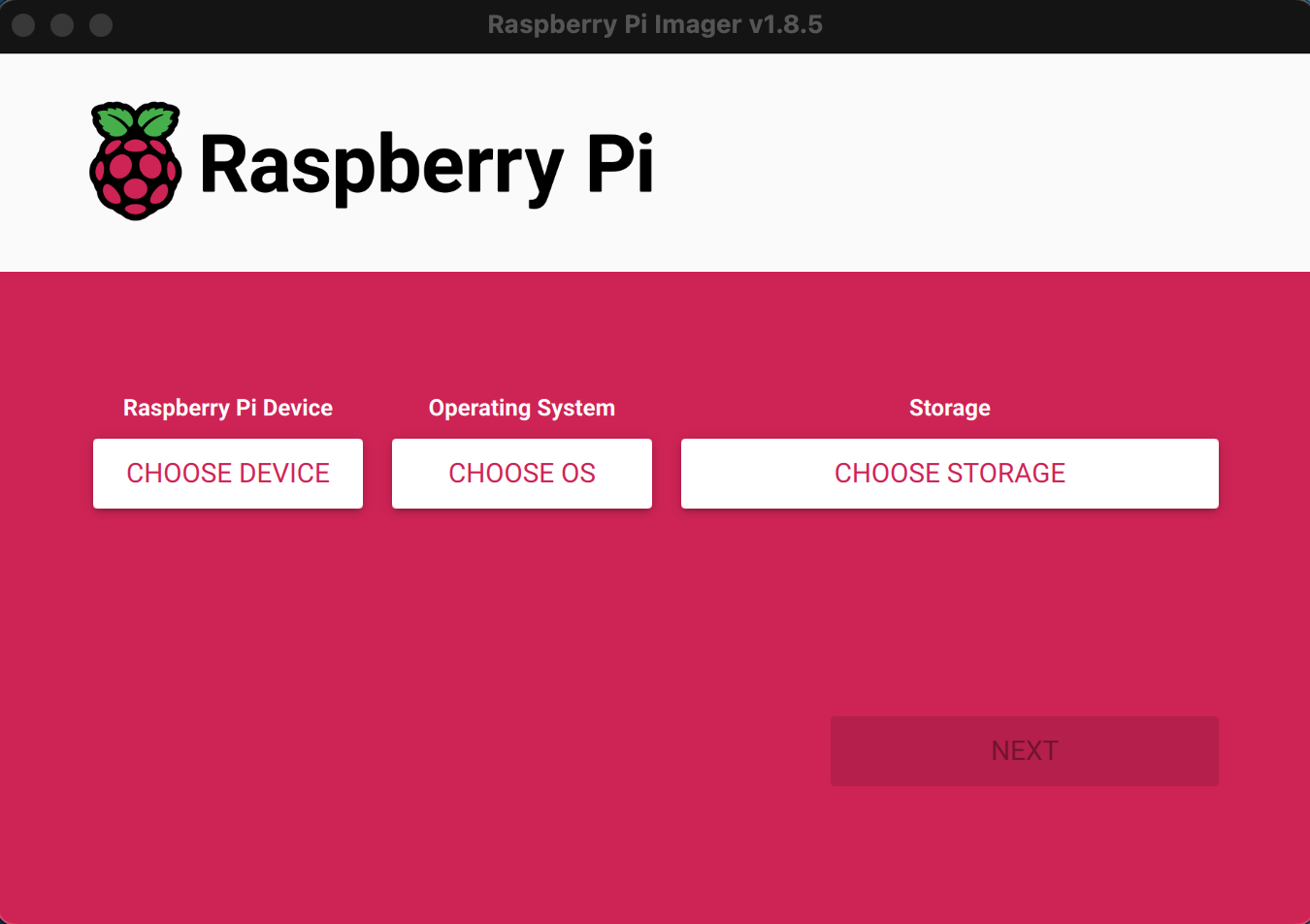
Write OS Image
The easiest way to create a bootable Raspberry Pi system is to use the Raspberry Pi Imager. This is a free tool that allows the selection of one of the many operating systems available for the Raspberry Pi and it can then be used to write the operating system to a SD card or HDD/SSD
The process starts by connecting the SATA to USB adapter the the SSD and then connecting the drive to the host computer. This makes the drive appear as an external USB drive.
Now start Raspberry Pi Imager:
Raspberry Pi Imager
Select the device we are going to create the image for, in this case this is the Raspberry Pi 5:
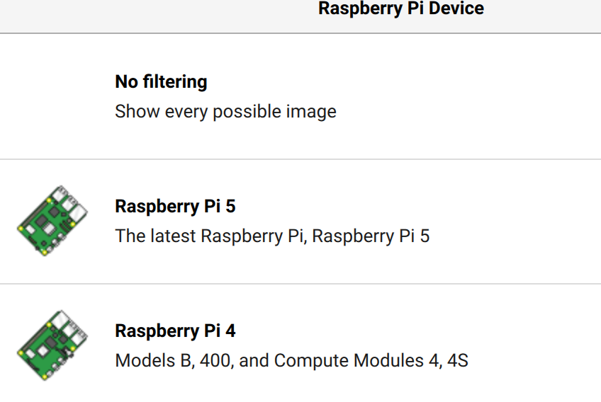
Select Device
The next step is to decide which operating system should be installed on the SSD. There are a large number of options and the selection will depend upon what you want to achieve. In this case we can use a basic system such as Raspberry Pi OS Lite. Firstly, select the Raspberry Pi (64-bit) operating system:
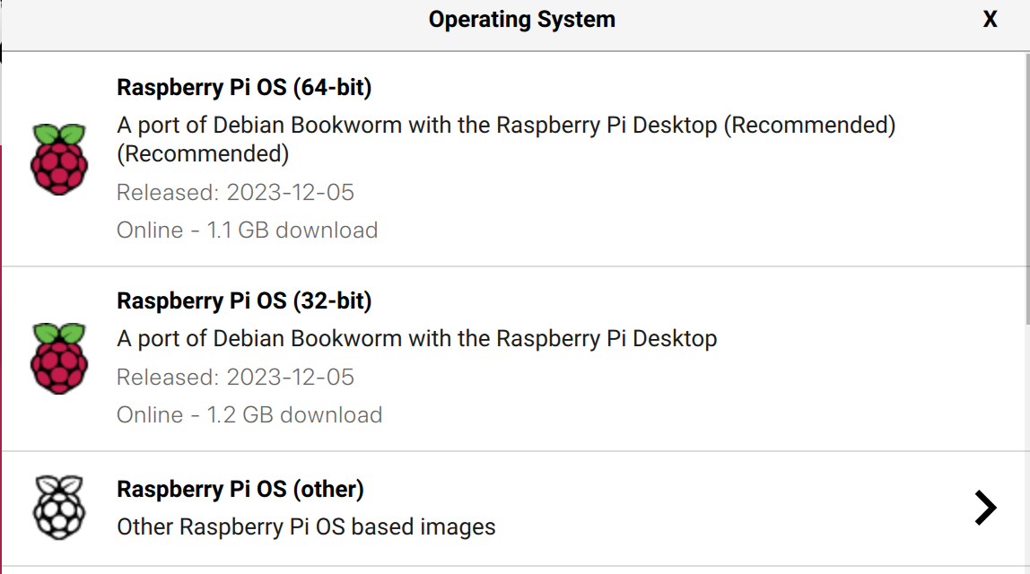
Select Operating System
Now refine this selection and select the Raspberry Pi OS Lite (64-bit):
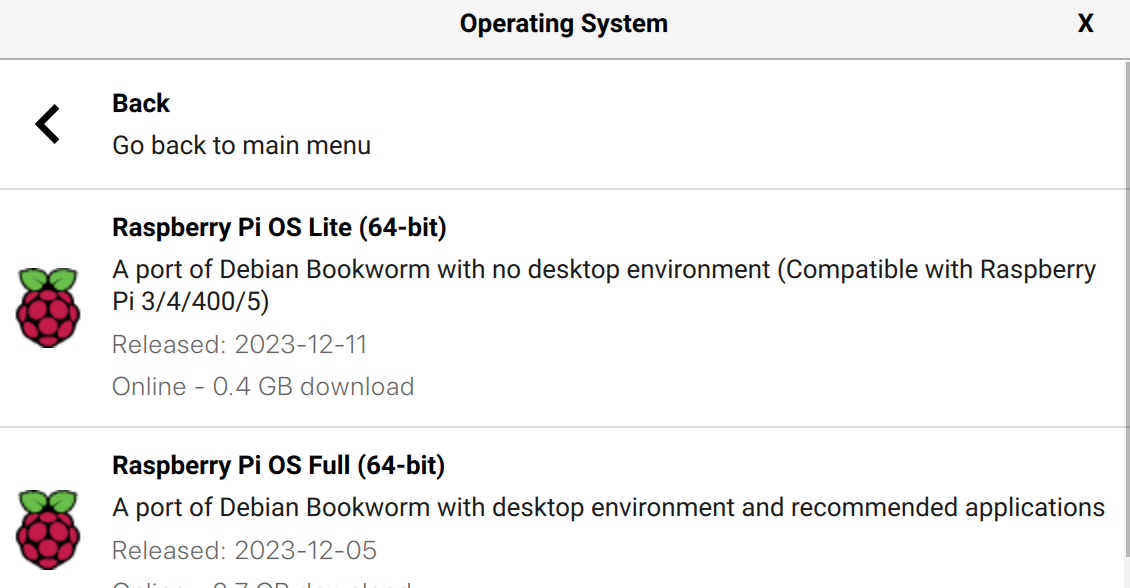
Select Raspberry Pi Lite
A basic system will be adequate as the device is intended to be run headless and so the desktop environment and applications are not required.
Next step is to select the storage device that the image will be written to. Once this is done we can move on to providing some configuration options for the operating system.
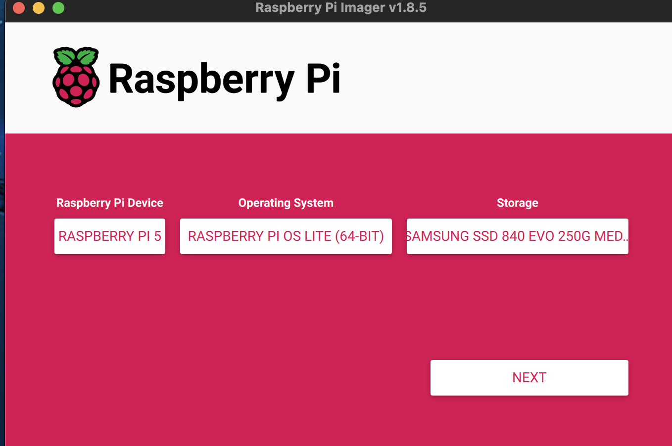
Ready For Configuration
Click the Next button to move on to the next step, editing the configuration.
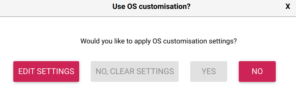
Edit Settings
Clicking Edit setting starts the editing process. The General options are presented first, here we can set the following:
- Hostname
- User name and password
- WiFi access point details
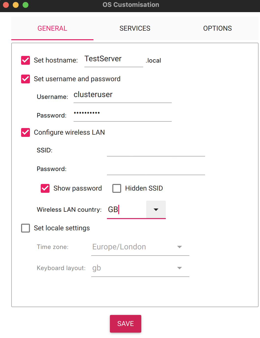
Customise General Settings
SSH should be enabled in order to run the system headless. This is enabled on the Services tab:
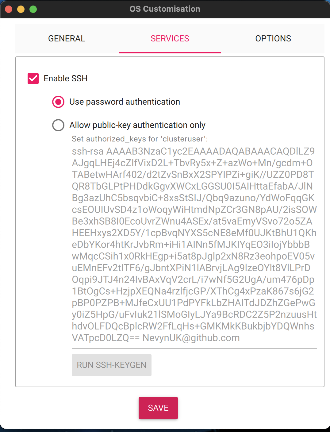
Customise Services
Clicking on Save now gives the option of applying the settings and start writing the image to the SSD:
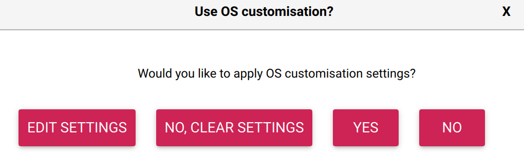
Apply Settings
The final step is to verify that the SSD can be erased:
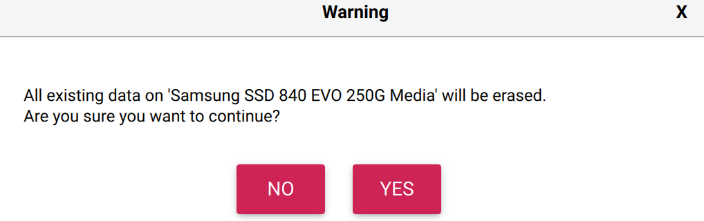
Confirm Media Erase
Control now passes back to the main window where the write and verification progress can be monitored:
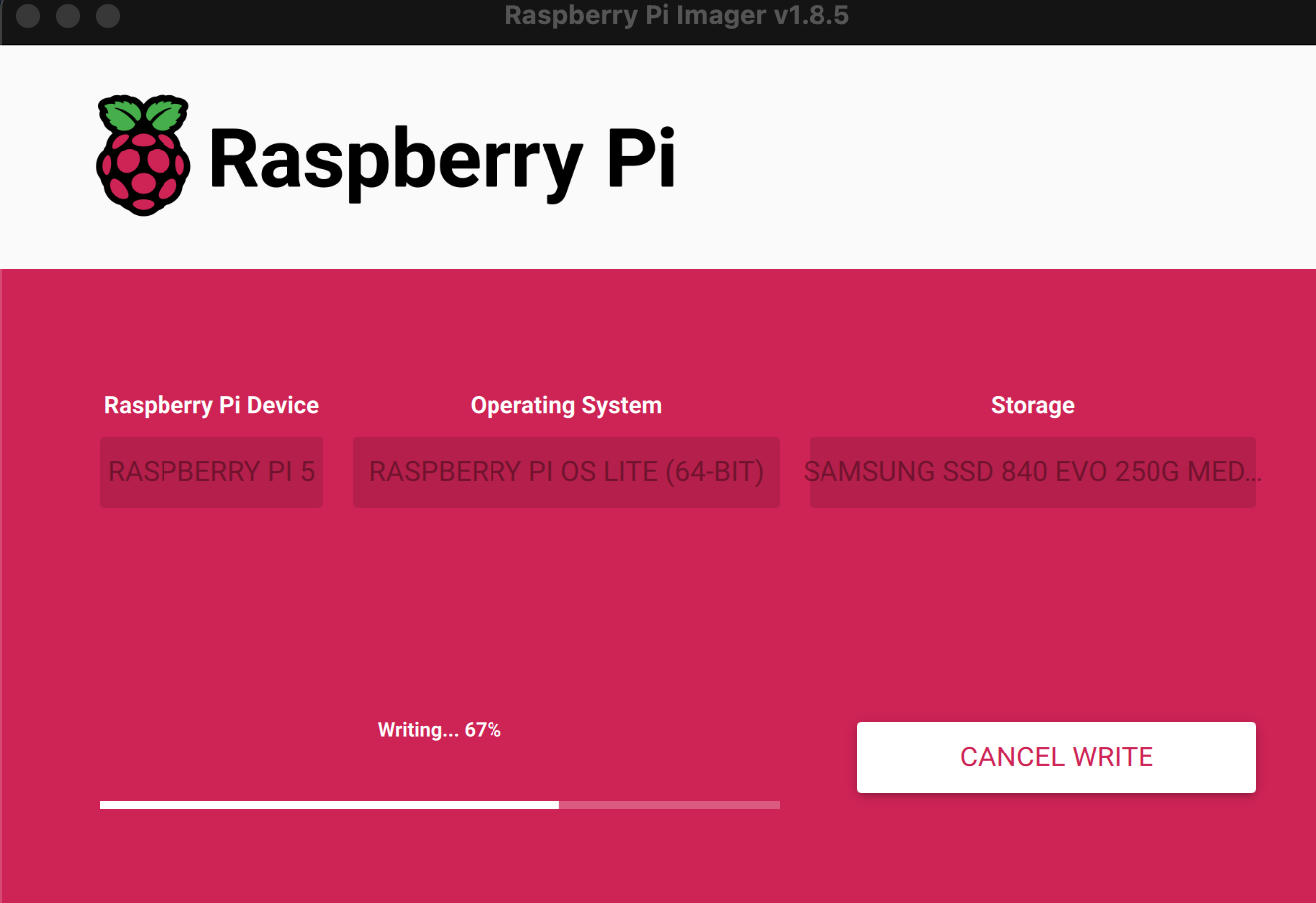
Writing OS
After a short while the the process will complete and Raspberry Pi Imager wil conform that the image has been written successfully and the drive can now be disconnected from the host computer and connected to the Raspberry Pi 5:
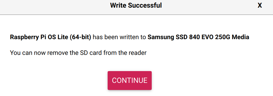
OS Write Successful
Conclusion
The whole process of creating the image is straightforward and only takes a few minutes. At the end of the process the Raspberry Pi is ready to boot.
The next step will be to start the installation and configuration of additional software tools and components. Something for the next post in this series.