Moving to KiCAD
Sunday, October 25th, 2015I have been a long time supporter of DesignSpark PCB for laying out my PCBs. Moving to the Mac meant that I had to look for an alternative or to use the PC emulator. Enter KiCad.
I needed a project in order to evaluate KiCAD, something small and inexpensive to manufacture will fit the bill. One project that needs completing is the LED cube. The 74HC595s in this project were always going to restrict the power of the cube. They have a limit of 125mW which limits either the number of LEDs that can be illuminated or the brightness of the LEDs. This can be easily overcome by either using a higher power 74HC595 or by connecting each of the LEDs to a transistor wired as a switch. The transistor as a switch idea gives some flexibility for future experimentation and so this is the direction we will take. Making this board for the cube would be expensive as it would be large, over 15cm x 15cm. A smaller version would prove the concept as well as the software.
8 LED Indicator Board
The 8 LED Indicator Board is a simple PCB containing all of the components that would be used in a large powered board. The board is simple, it takes a signal for each of the 8 LEDs, power and ground. Any high signals turn the transistor on and illuminates the appropriate LED. The schematic for a single switch is as follows:
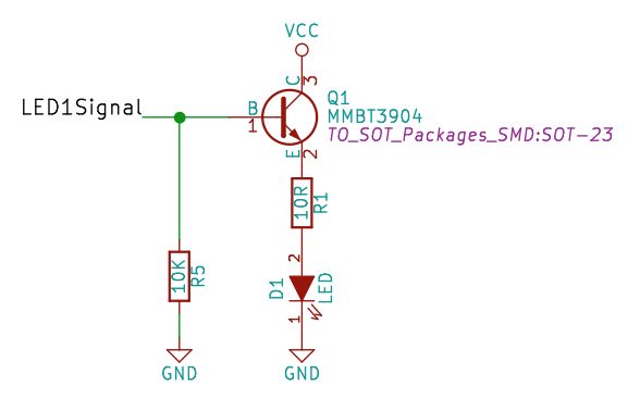
Simple Transistor Switch
The board contains 8 of these switches along with connectors for the power and signals, adding seven more and some connectors gives the following:
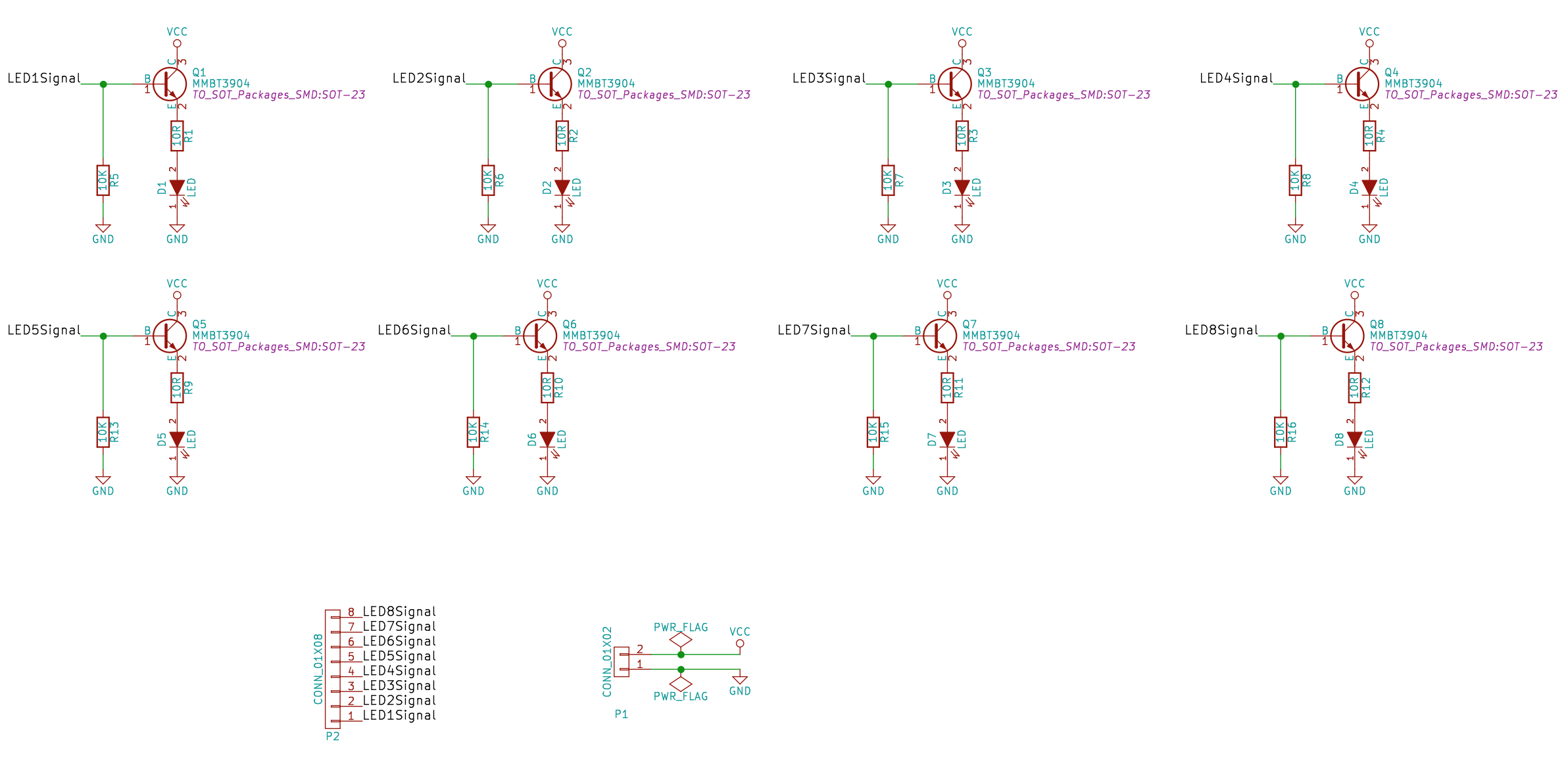
8 Transistor Switches
The next step in the process is to convert this design to a PCB layout. Normally (with DesignSpark) I would just jump from the schematic straight to the PCB layout. With KiCAD it is necessary to perform two additional (for me) actions. The first is to annotate the components in the schematic. The second is to associate a footprint to each of the components. PCB layout can commence once this has been completed.
A few hours later:
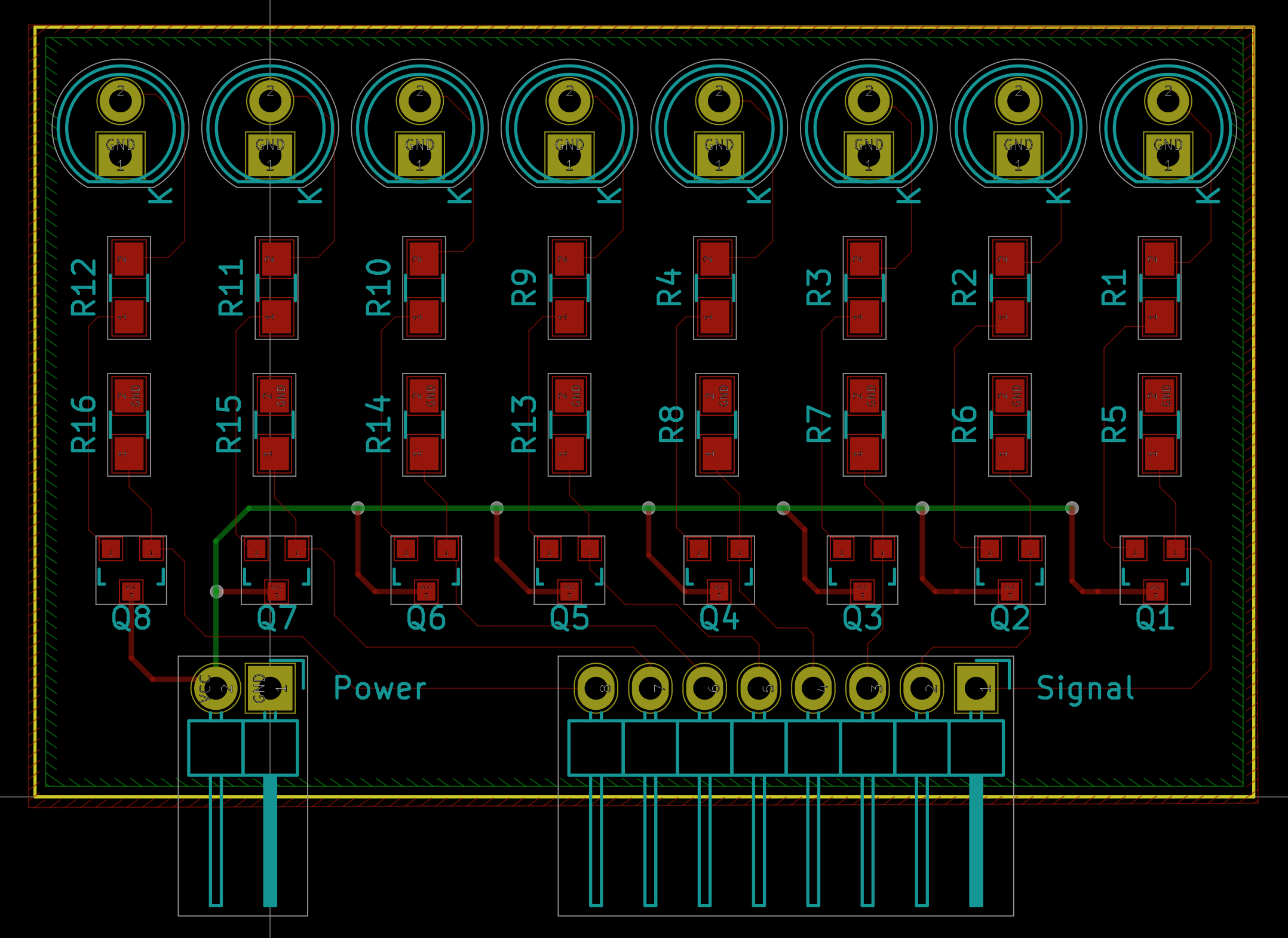
8 LED Transistor Switch PCB Layout
There is even a 3D viewer with an impressive set of models built in:
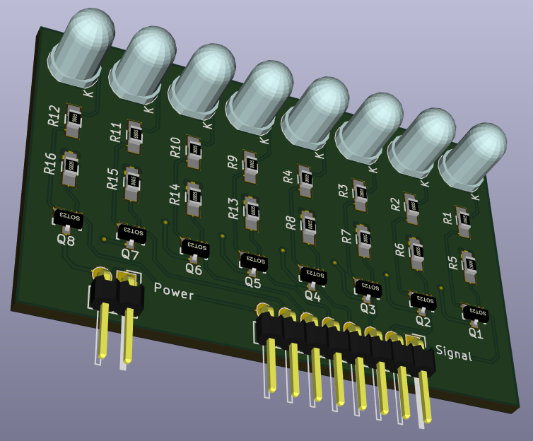
8 LED Switch in 3D
So far, so good, the final step is to generate the gerbers, send for manufacture and wait.
Conclusion
Moving from one software suite to another is always an interesting process. Old habits such as key strokes, menu locations etc are difficult to break. I certainly found some aspects of KiCAD a little frustrating but as ever, there is always Google.
The gerber files have been sent to manufacture. The good news is that they were accepted straight away and have been through the manufacturing process. They are currently somewhere between China and the UK. I expect to see them in about 1 week (assuming the usual delay between ordering and shipping).
There are some issues I have found with the software:
- The PCB Designer drains the battery on the Mac significantly faster than the Schematic layout tool.
- Every now and then the PCB layout tool will start to zoom in (or out) seemingly at random.
- Creating a new, empty component library is not as intuitive as it could be.
In fairness though there are some thing which I really did like:
- Schematic editor is simple to use
- Large component library
- 3D Viewer
- Easy to create new components
- It only took a week to go from nothing to gerbers
All in all, this has been a positive experience although painful at times. The only thing remaining is to see how the boards turn out.

