RSS

Archive for the ‘Tips’ Category

KiCAD Relative Positioning

Sunday, March 10th, 2024

KiCAD Positioning Banner

Most of the PCBs I make have mounting holes in the final layout to allow the boards to be firmly attached to 3D printed cases or mounts. When I first started using KiCAD I found it difficult to position the arc edge cuts around the mounting holes accurately. This was not too critical but it was a little annoying. The error in positioning the arcs was minor and is difficult to see but it would be good to fix the problem.

This was something I finally worked out in the last design I sent to manufacture and thought it would be something others might want to know about.

Board Layout

Most of my designs usually result in a square or rectangular board. The boards are simple and don’t really need to fis an irregularly shaped case. So most of the time I am trying to place a hole at the corner of say a square and then place an edge cut around the hole, something like this:

PCB with two mounting holes

PCB with two mounting holes

Placing the mounting holes is a simple case of editing the x and y positions of the mounting hole and ensuring that the holes are lined up correctly. The edge cuts are a little more difficult to position consistently when placing them by hand.

Accurate Edge Cuts

As noted above, the first stage is to place the mounting holes on a rectangular grid and using the x and y positions to place the holes. Next step is to create an arc centred on one of the mounting holes with the appropriate radius. This can be done in using the centre of the mounting holes as the starting point and then sweeping an arc through 90 degrees around the hole:

Arc and Hole

Arc and Hole

Next up we duplicate the arc, rotate it through 90 degrees and move to one of the opposite mounting holes:

Duplicated arcs

Duplicated arcs

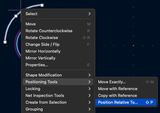
As you can see, the duplicated arc is not centred on the opposite mounting hole. We now use the positioning tools to align the arc with the mounting hole. Start by selecting the arc and then right click to bring up the context menu and select Position Relative To… from the context menu:

Positioning context menu

Positioning context menu

From the positioning dialog click on the Select Item button:

Select item button

Select item button

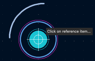
Next, select the reference item, in this case it is the mounting hole:

Select the reference item

Select the reference item

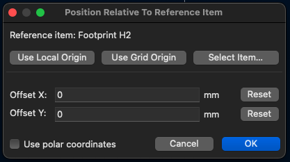
The positioning dialog will now reappear with the reference item selected. Ensure that the Offset X and Offset Y are both set to 0 and click OK.

Position dialog box

Position dialog box

The arc should now move and be centred on the mounting hole.

Final arc position

Final arc position

Finally, repeat for the remaining 2 mounting holes.

Conclusion

This method allows for the board outline to be defined more accurately then lining up the arcs by eye. It is simple to do and only takes a few minutes to complete. The arcs can then be used as the anchors for the linear edges of the board.

This technique is also useful for positioning other parts on any design.

Photo to Pencil Drawing With Affinity Photo

Sunday, February 11th, 2024

Pencil Drawing Banner

Another aide memoir, how to convert a photo into a pencil sketch using Affinity Photo. I don’t do this often and so I always forget the steps.

In the following I will refer to the Mac keystrokes which use the CMD key, on the PC use the CTRL key.

Starting Point

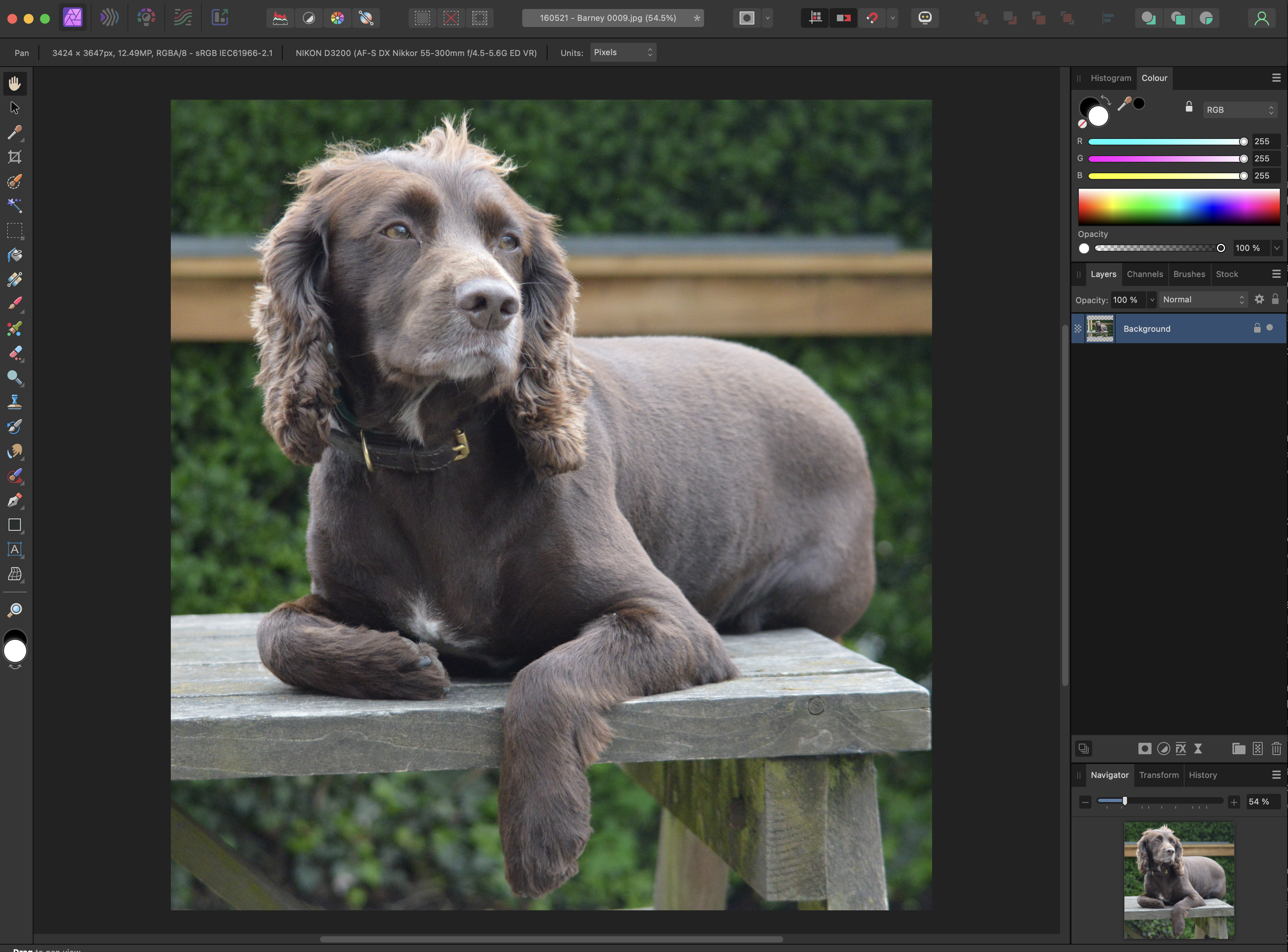
This example will use a photo of a working cocker spaniel:

Original Image

Original Image

The image has a reasonable amount of detail and will be a challenge.

Essential Steps

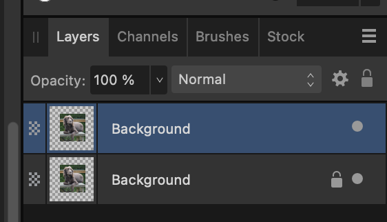
Form me, the first step when working with any photograph it to create a duplicate of the original and make sure that the original is locked.

Shortcut: CMD+J

Duplicate Layer

Duplicate Layer

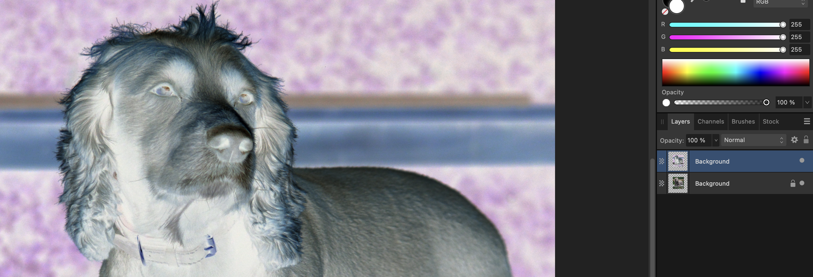
Next step, invert the image on the duplicate layer.

Shortcut: CMD+I

Invert duplicate layer

Invert duplicate layer

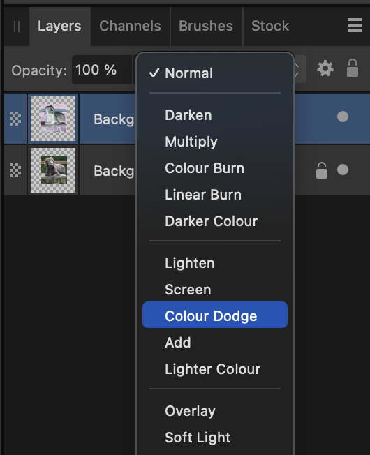
Next up, change the blend mode of the duplicate layer to colour dodge.

Colour Dodge

Colour Dodge

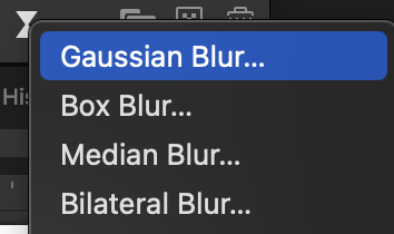
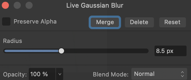
The image should now turn white. Now add a Gaussian blur to the duplicate layer.

Gaussian Blur

Gaussian Blur

Use the slider to change the radius until you are happy with the effect.

Change Blur Radius

Change Blur Radius

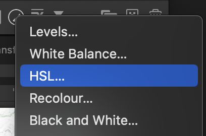
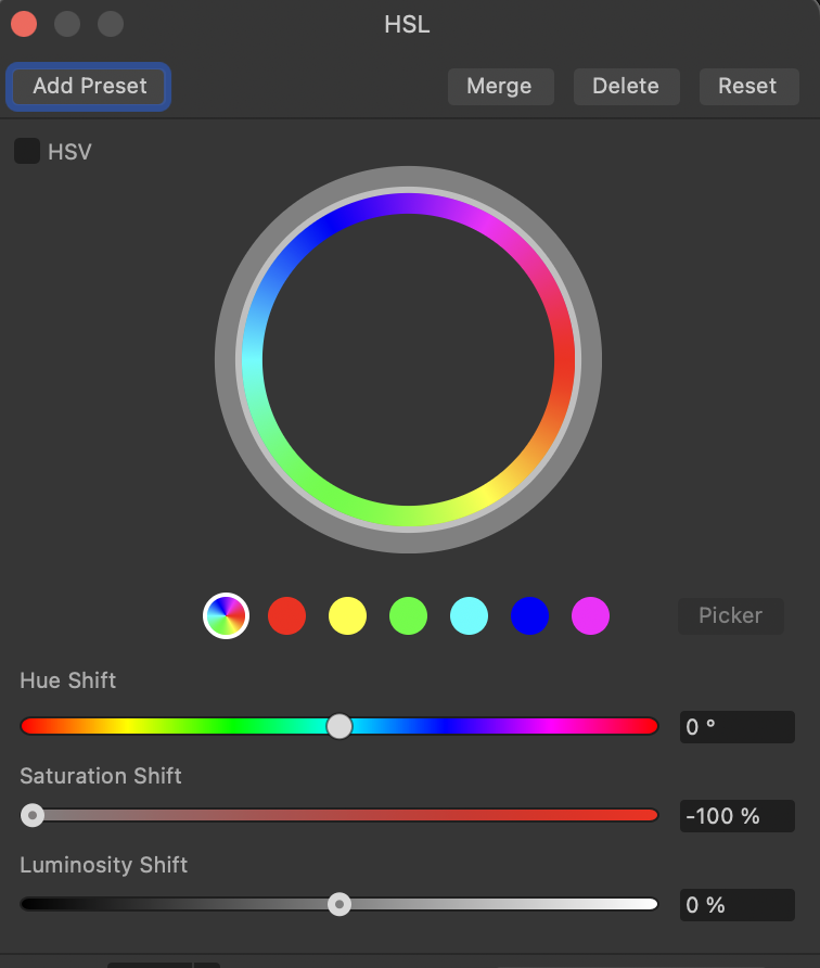
At this point the image still has some colour in it. Adding a HSL adjustment and reducing the saturation to 0% will remove the colour.

Add HSL Adjustment

Add HSL Adjustment

Set saturation to 0%

Set saturation to 0%

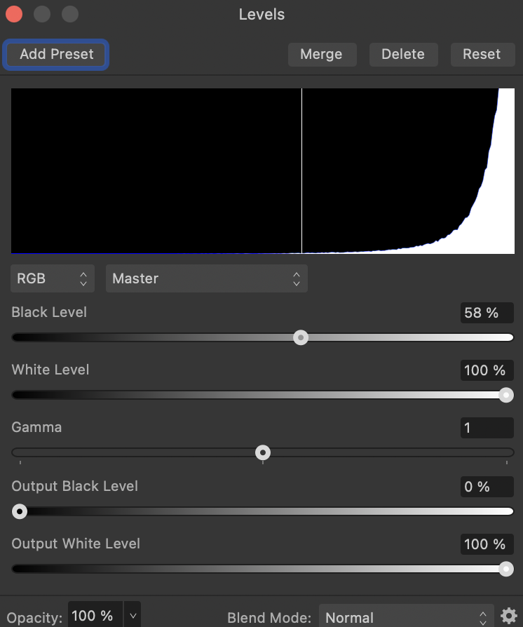
The final step is to add a Levels Adjustment:

Adjust Levels

Adjust Levels

and adjust the black level:

Change the Black Level

Change the Black Level

Here is a zoomed in section of the final image:

Image post levels adjustment

Image post levels adjustment

Optional Additional Adjustments

There are some additional adjustments that can be made to give the image the appearance of an actual pencil drawing:

  • Add a paper like canvas to the image
  • Use a mask layer to paint out some of the background around the edges giving a blurred edge
  • If the edge of the image is predominantly white then maybe use the inpainting tool to remove any slightly grey areas in the background

Conclusion

Here is the full image with just the essential adjustments:

Final Image

Final Image

Dell 1320c on Mac OS

Wednesday, November 15th, 2023

Add Dell 1320c Header

Upgrading machines is always an interesting experience, reinstalling software and drivers. The latest update from an Intel Mac to Apple silicon was no exception. The majority of the process went to plan with the only major issue being the installation of the Dell 1320c printer driver.

Some History

The Dell 1320c printer is a fairly old colour laser printer and this device is about 12 years old but it has seen very light service. Replacing a such a lightly used machine is not only environmentally unfriendly but also an unnecessary expense.

Driver support for this printer has always been patchy on newer machines which is understandable. The trick with this printer is not to install it as a Dell 1320c printer but instead use the Xerox C525 driver.

This year has seen several failed attempts to install the driver on Apple silicon machine with the latest attempt working, hence this post in case it helps others (and also my future self).

Installing the Driver

The driver can be installed by following these steps:

1 – Open the Printer and Scanner Settings

Open the Printer and Scanner settings and click the Add Printer, Scanner or Fax.. button.

Add New Printer

Add New Printer

2 – Add Printer Properties

The printer being installed in a network printer and completing the IP address allows the computer to find the printer and complete some of the printer properties.

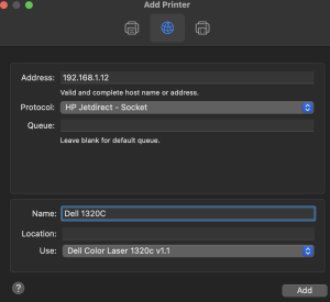
Add Printer Dialog

Add Printer Dialog

Two setting need to be changed. The first is the Protocol, this should be set to HP Jetdirect – socket.

The second setting that needs to be changed is the driver. Click the Use drop down and select Select Software…. This will present you with the Printer Software dialog.

3 – Install the Xerox Driver

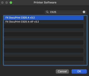
In the Printer Software dialog, search for C525 and select the Xerox C525 A v3.2 driver.

Printer Software Dialog

Printer Software Dialog

Click the OK button to add the printer.

The only thing is to test the installation by printing a test page.

Conclusion

Getting the Dell 1320c driver installed is not difficult, it is simply a case of knowing the tricks to get it working. This is something that is only performed every few years and hopefully this will help the next time this driver need to be installed on a new machine.

Mac Remote Access

Sunday, October 15th, 2023

SSH Login Command

This blog serves two purposes:

  • Sharing information that I hope is useful to others
  • Aide-Memoire for yours truly

This post falls into the second group, something I’ve done in the past but forgotten.

Background

The current project requires the test environments to be expanded. Several of the environments are running on Raspberry Pi SBC which is feasible now that they are available in volume once again. There is one exception, a Mac Mini with a M1 processor. This environment allows the usual tests to be run in the same manner as the Raspberry Pi boards. It also gives the ability to build the code and attach a debugger to the board invaluable for tests that are known to be failing and need to run for an extended period of time.

This sort of setup is ideal for running headless, no monitor, keyboard or mouse; we can just use MacOS screen sharing and ssh.

What is Wrong?

Enter a new (well secondhand) Mac Mini. Setup went well, attached a keyboard and mouse and ran through the setup process with no issues. Logged on to the Mac and all is well. A few configuration tweaks to enable screen sharing and remote login were required, nothing too complex, just a case of setting the right permissions.

Next step, test the remote connection. Screen sharing started OK and the Mac appeared on the network with file sharing enabled. Time for a reboot.
System rebooted OK, time to browse the network.

The new machine was not showing in the network browser and ssh was able to establish the connection.

Back to the still connected keyboard and mouse to log on. Once logged in the system once again appeared in the network browser and screen sharing and ssh worked flawlessly.

Time for another reboot and the same thing happened, machine booted OK but nothing appeared on the network until a successful login through the attached keyboard and mouse.

The Solution

This is where it gets odd. Apparently, you have to turn FileVault off. That’s right you have to turn the disc encryption off in order to enable fully remote logon.

FileVault is turned on automatically during the MacOS installation processes which makes sense. Disc encryption will make it harder for a malicious actor to recover sensitive information from a machine, so disc encryption on modern machines is good. The side effect of this is that you must logon to the Mac via an attached keyboard before it will turn up on the network.

Conclusion

I have a solution of sorts but I do find it odd that disc encryption must be disabled before remote services can be enabled on the Mac. After all, if you require remote access to a system then you are likely to be putting the physical machine in a location where access is going to be difficult.

Threaded Inserts and 3D Printed Mounts

Saturday, April 1st, 2023

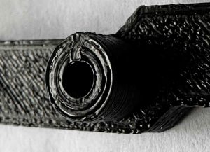
Threaded insert in pillar

Threaded insert in pillar

Way back in 2019, Hackaday posted an article on Threading 3D Printed Parts: How to Use Heat-set Inserts which discussed how to use brass inserts in 3D printed parts to make connecting parts easier and more robust. The article presented the changes you should make to prints in order to make adding the inserts easier to locate and some of the tools that could be purchased to make using these inserts easier.

I have been using these type of inserts for a few years now and this month came up with a slight variation on the method discussed in the above article. The process of laying out the part remains the same, the change made is to the method of fixing the brass threaded insert into the 3D printed part.

The original article discussed using special tools for heating the threaded insert and pushing the heated part into the 3D printed model. This article presents an alternative to a specialist part by using nothing more than some scrap protoboard. The beauty of this technique is that it does not require any special tools.

Requirement

I regularly use a number of different microcontroller development boards and debug probes for firmware development. These boards commonly have components on the bottom of the boards and / or through hole parts where the legs of the components protrude through the board and potentially damage desks / work surfaces.

A 3D printed mount or frame keeps any components away from work surfaces protecting them from scratches and also reduces the possibility of shorting components on the boards themselves.

The process will be illustrated with a Spresense board and external adapter.

The technique should meet the following requirements:

  • Use tools that any maker should have in their workshop
  • Present a flat surface around the insert
  • Keeps tools clear of any melted material

3D Design

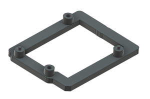
The external Spresense adapter board has four mounting holes and the intention is to use two of the holes to acts as locators and two holes to fix the board in place. The mount will have four pillars under the holes in the external adapter board. Two of these will have printed pins to act as locators. Two of the pillars will use threaded inserts to allow screws to fix the board in place. A picture is worth a thousand words so here is how the final design looks:

Fusion 360 design for Spresense mount

Fusion 360 design for Spresense mount

Adding the Threaded Insert

The starting point of the process is the 3D printed frame with the objective of embedding the threaded insert securely into the printed part. The pillar is a simple cylinder with a hole running through to the base of the frame.

Pillar on mount

Pillar on mount

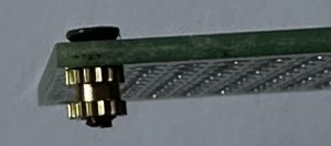
The first step is to prepare the threaded insert for insertion into the frame. This is done by using a screw matching the insert mating the two through a piece of protoboard:

Threaded insert on protoboard

Threaded insert on protoboard

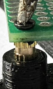
Next up, the insert in placed in the hole in the pillar and the protoboard is used to hold the insert in place. The tip of a hot soldering iron is placed on the head of the screw and a slight pressure is applied using the protoboard:

Adding threaded insert (stage 1)

Adding threaded insert (stage 1)

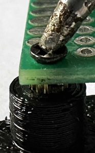
Continue applying pressure using the protoboard as the part sinks into the 3D printed part:

Adding threaded insert (stage 2)

Adding threaded insert (stage 2)

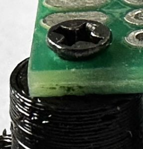
By continuing to apply pressure, the protoboard will finally hit the top of the pillar. At which point remove the soldering iron and hold the protoboard in place for a few seconds. This will allow the PLA to set around the insert.

Adding threaded insert (stage 3)

Adding threaded insert (stage 3)

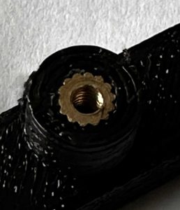
Finally, remove the screw from the board to reveal the insert which should now be firmly embedded into the pillar.

Threaded insert in pillar

Threaded insert in pillar

Conclusion

The technique presented uses simple tools which are available in many makers workshops or are relatively cheap to purchase. It achieves the objectives set out earlier in this post as well as those in the original Hackaday article.

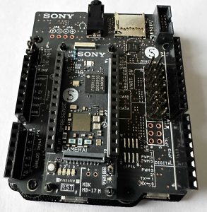
Finally, here is the assembled board and mount.

Spresense external carrier board on mount

Spresense external carrier board on mount