RSS

Posts Tagged ‘Raspberry Pi’

Repeatable Deployments 3 – Adding NVMe Drive Automatically

Monday, July 1st, 2024

Repeatable Deployments Part 3 - Adding NVMe Drive Automatically Banner

This latest chapter in the Repeatable Deployments series looks at automating the steps discussed in the Raspberry Pi and NVMe Base post. The previous post investigated the manual steps necessary to add a PCIe drive, here we will look at automating the setup process.

TL;DR The scripts and instructions for running them can be found in the AnsibleNVMe GitHub repository.

Automation Options

The two main (obvious) options for automation in this case would be:

  • Shell scripts
  • Ansible

In this post we will look at using Ansible as it allows remote installation and configuration without having to install scripts on the target machine.

The Hardware

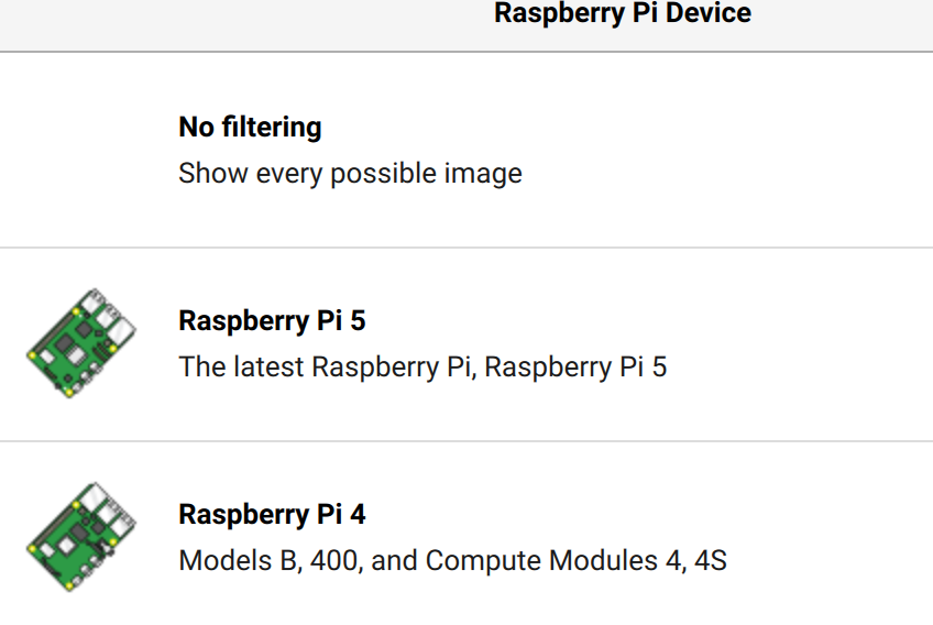
The installation hardware will be based around the Raspberry Pi 5 as the PCIe bus is required for the NVMe base and associated SSD:

  • Raspberry Pi (3, 4 or 5)
  • 256 GByte SATA SSD
  • SATA to USB adapter
  • Cooling fan (for the Raspberry Pi 5)
  • NVMe Base and 500GByte M2 drive
  • Power Supply
  • Ethernet cable
  • 3D printed mounts to bring everything together

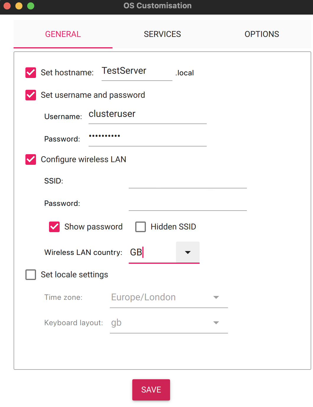
For the purpose of this post we will be configuring the system with the following credentials:

  • Hostname: TestServer500
  • User: clusteruser

The password will be stored in an environment variable and on a Mac this is setup by executing the following command:

export CLUSTER_PASSWORD=your-password

The remainder of this post will assume the above names and credentials but feel free to change these as desired.

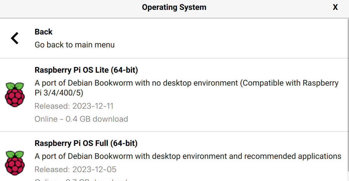
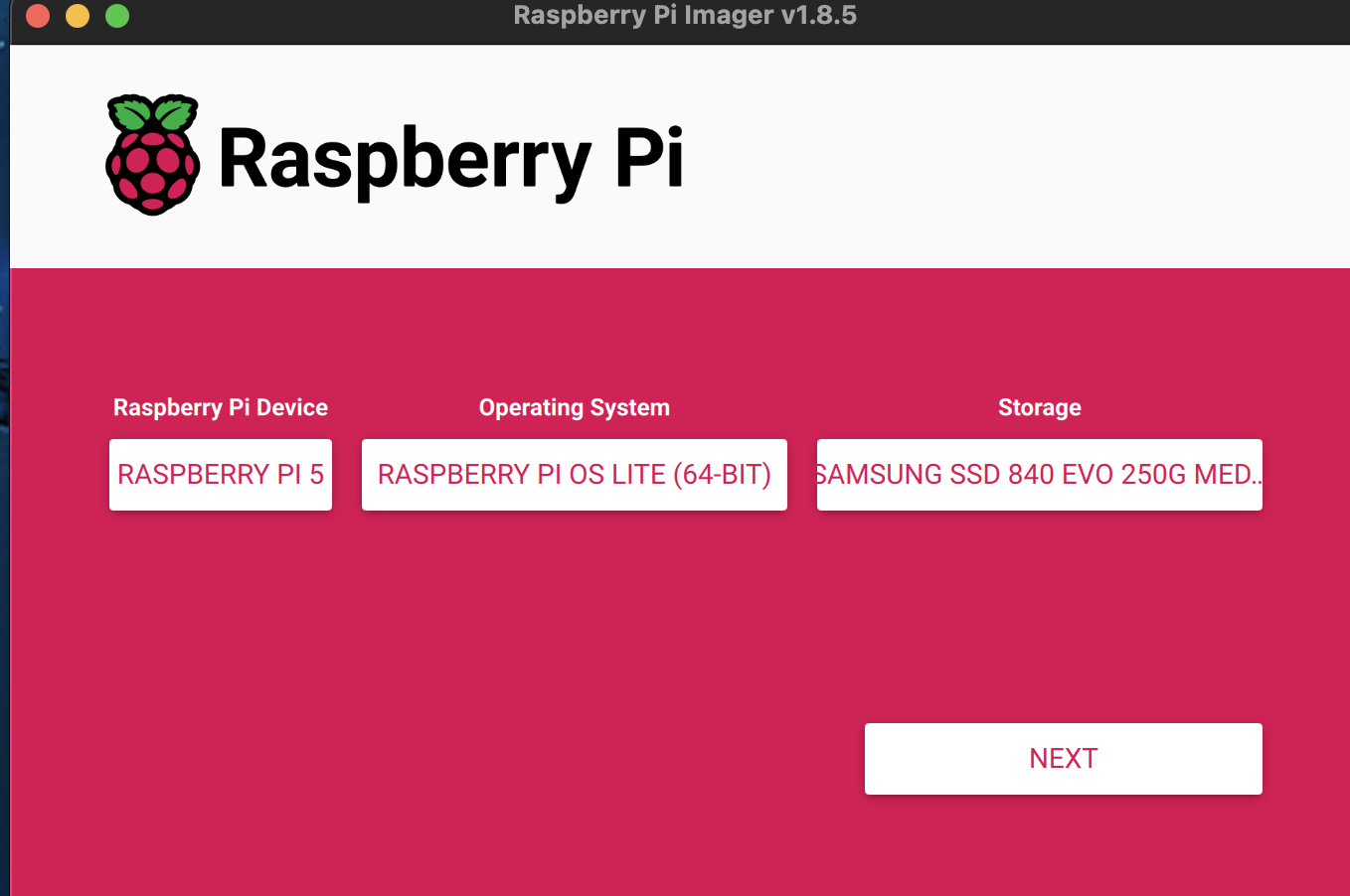
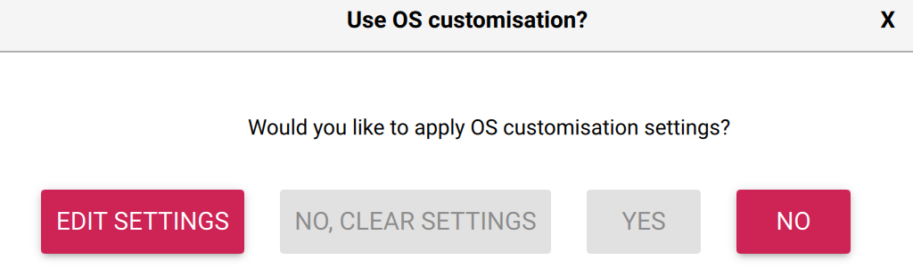
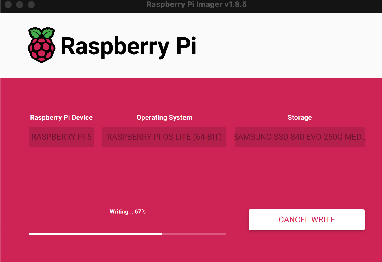
Step 1 – Install the Base Operating System

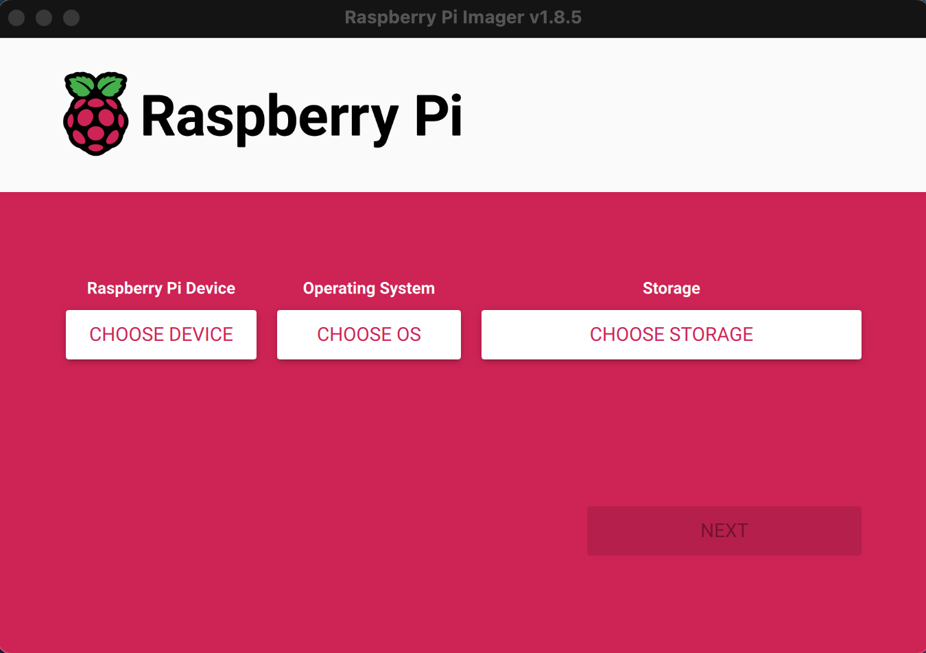
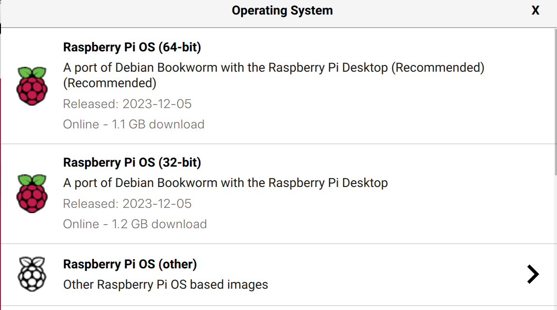
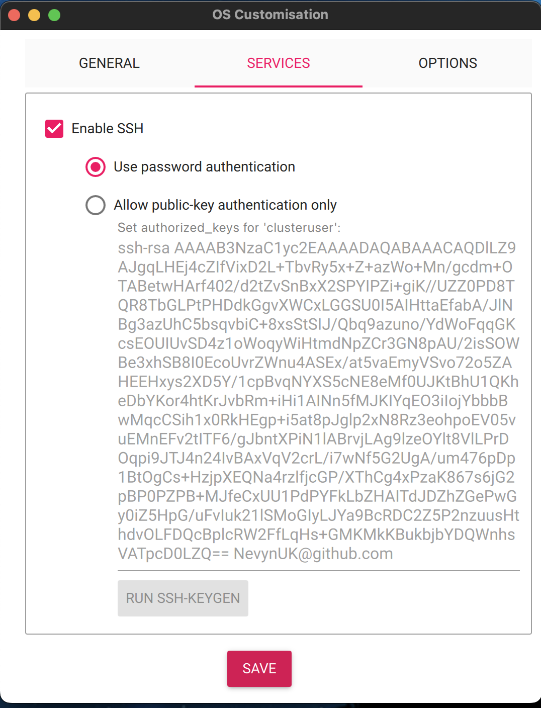
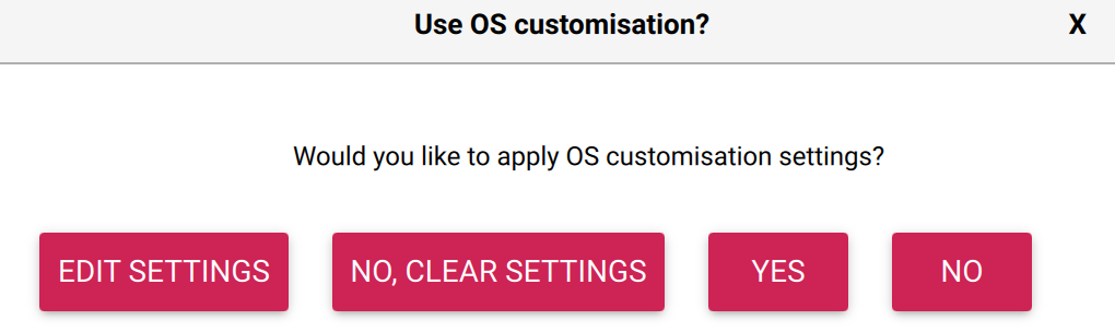
The operating system is installed following the same method as described in part 1 of this series. Simply ensure that the hostname, user name and password parameters are set to those noted above (or with your substitutions).

Step 2 – Ensure SSH Works

The next thing we need to do is to check that the Raspberry Pi boots and that we can log into the system. So apply power to the board and wait for the board to boot. This normally takes a minute or two as the system will boot initially and then expand the file system before booting two more times.

Time for the first log on to the Raspberry Pi with the command:

ssh testserver500.local

If this is the first time this device has been setup with the server name then you will be asked to accept the certificates for the host along with the password for the Raspberry Pi.

The authenticity of host 'testserver500.local (fe80::67b6:b7f4:b285:2599%en17)' can't be established.
ED25519 key fingerprint is SHA256:gfttQ9vr7CeWfjyPLUdf5h2Satxr/pRrP2EjbmW2BKA.
This key is not known by any other names.
Are you sure you want to continue connecting (yes/no/[fingerprint])? yes
Warning: Permanently added 'testserver500.local' (ED25519) to the list of known hosts.
clusteruser@testserver500.local's password:
Linux TestServer500 6.6.20+rpt-rpi-2712 #1 SMP PREEMPT Debian 1:6.6.20-1+rpt1 (2024-03-07) aarch64

The programs included with the Debian GNU/Linux system are free software;
the exact distribution terms for each program are described in the
individual files in /usr/share/doc/*/copyright.

Debian GNU/Linux comes with ABSOLUTELY NO WARRANTY, to the extent
permitted by applicable law.
clusteruser@TestServer500:~ $

Answer yes to accept the certificates and then enter the password at the following prompt.

If the machine name has been used before, or if you are trying repeat deployments then you will receive a message about certificate errors:

@@@@@@@@@@@@@@@@@@@@@@@@@@@@@@@@@@@@@@@@@@@@@@@@@@@@@@@@@@@
@    WARNING: REMOTE HOST IDENTIFICATION HAS CHANGED!     @
@@@@@@@@@@@@@@@@@@@@@@@@@@@@@@@@@@@@@@@@@@@@@@@@@@@@@@@@@@@
IT IS POSSIBLE THAT SOMEONE IS DOING SOMETHING NASTY!
Someone could be eavesdropping on you right now (man-in-the-middle attack)!
It is also possible that a host key has just been changed.
The fingerprint for the ED25519 key sent by the remote host is
SHA256:<sha256-key>
Please contact your system administrator.
Add correct host key in /Users/username/.ssh/known_hosts to get rid of this message.
Offending ECDSA key in /Users/username/.ssh/known_hosts:35
Host key for testserver500.local has changed and you have requested strict checking.
Host key verification failed.

This can be resolved by editing the ~/.ssh/known_hosts> file and removing the entries for testserver500.local, saving the file and retrying.

A final step is to copy the local machine ssh keys to the Raspberry Pi. This can be done with the command:

ssh-copy-id testserver500.local

This command provides access to the Raspberry Pi, from the current machine, without needing to enter the password so keep in mind the security implications. Executing the above command will result in output something like:

/usr/bin/ssh-copy-id: INFO: attempting to log in with the new key(s), to filter out any that are already installed
/usr/bin/ssh-copy-id: INFO: 1 key(s) remain to be installed -- if you are prompted now it is to install the new keys
clusteruser@testserver500.local's password: <enter you password here>

Number of key(s) added:        1

Now try logging into the machine, with:   "ssh 'clusteruser@testserver500.local'"

Where the password for the Raspberry Pi user was entered when prompted. These two steps are required for Ansible to work correctly (at least from a Mac).

Step 3 – Update the System

At this point the Raspberry Pi has the base operating system installed and we have confirmed that the system can be accessed from the local host computer. The next step is to ensure that the operating system is updated with the current patches and the EEPROM is updated to the latest to allow access to the NVMe Base.

From the previous post, Raspberry Pi and NVMe Base, we know that we can do this with the commands:

sudo apt get update -y
sudo apt get dist-upgrade -y
sudo raspi-config nonint do_boot_rom E1 1
sudo reboot now

The first thing to note is that in the Ansible scripts we will be using privilege elevation to execute command with root privilege. This means that we do not need to use sudo to execute the commands in the Ansible scripts. So we start by creating a YAML file with the following contents:

---
- name: Update the Raspberry Pi 5 OS and reboot
  hosts: raspberrypi
  become: true
  tasks:
    - name: Update apt caches and the distribution
      apt:
        update_cache: yes
        upgrade: dist
        cache_valid_time: 3600
        autoclean: yes
        autoremove: yes
        
    - name: Update the EEPROM
      command: raspi-config nonint do_boot_rom E1 1

    - name: Reboot the Raspberry Pi
      reboot:
        msg: "Immediate reboot initiated by Ansible"
        reboot_timeout: 600
        pre_reboot_delay: 0
        post_reboot_delay: 0

There are a number of websites discussing Ansible scripts including the Ansible Documentation site so we will just look at the pertinent elements of the script.

hosts: raspberrypi defines the host names / entries that this section of the script applies to. We will define this later in the inventory.yml file.

become: true is the entry that tells Ansible that we want to execute the tasks with elevated privileges.

tasks defines a group of tasks to be executed on the Raspberry Pi. These tasks will be a combination of actions that Ansible is aware of as well as commands to be executed on the Raspberry Pi. In this script the tasks are:

  • Use apt to update the distribution
  • Execute the command to update the Raspberry Pi EEPROM
  • Reboot the Raspberry Pi to ensure the updates are applied

Now we have the definition of the tasks we want to execute we need to define the systems we want to run the script against. This can be done using an inventory script. For the single Raspberry Pi this is a simple file and looks like this:

[raspberrypi]
testserver500.local ansible_user=clusteruser ansible_ssh_pass=$CLUSTER_PASSWORD ansible_python_interpreter=/usr/bin/python3

The above contains a number of familiar entries, the server and user names. ansible_ssh_pass references the environment variable set earlier. The final entry, ansible_python_interpreter=/usr/bin/python3, prevents a warning from Ansible about the Python version deployed on the Raspberry Pi. This warning looks something like:

[WARNING]: Platform linux on host testserver500.local is using the discovered Python interpreter at /usr/bin/python3.11, but future installation of another Python interpreter could change the meaning of that path. See https://docs.ansible.com/ansible-core/2.17/reference_appendices/interpreter_discovery.html for more
information.

We are now ready to use Ansible to update the Raspberry Pi using the following command:

ansible-playbook -i inventory.yml UpdateAndRebootRaspberryPi.yml

If all goes well, then you should see something like the following:

PLAY [Update the Raspberry Pi 5 OS and reboot] ******************************************************************************************************************************

TASK [Gathering Facts] ******************************************************************************************************************************
ok: [testserver500.local]

TASK [Update apt caches and the distribution] ******************************************************************************************************************************
changed: [testserver500.local]

TASK [Update the EEPROM] ******************************************************************************************************************************
changed: [testserver500.local]

TASK [Reboot the Raspberry Pi] ******************************************************************************************************************************
changed: [testserver500.local]

PLAY RECAP *******************************************************************************************************************
testserver500.local        : ok=4    changed=3    unreachable=0    failed=0    skipped=0    rescued=0    ignored=0

Step 4 – Format and Configure the Drives

We can now move on to configuring the system to access the NVMe drives.

Configure PCIe Gen 3 support

The NVMe Base can be run using PCIe Gen 3 support. This is experimental and not guaranteed to work although in my experience there are no issues with the drive supplied with the NVMe Base. The following code adds the appropriate entried in the /boot/firmware/config.txt file.

- name: Ensure pciex1_gen3 is enabled in /boot/firmware/config.txt
  blockinfile:
  path: /boot/firmware/config.txt
  marker: "# {mark} ANSIBLE MANAGED BLOCK"
  block: |
      dtparam=pciex1_gen=3
  insertafter: '^\[all\]$'
  create: yes

Format the Drive and Mount the File System

The next few steps executes the command necessary to format the drive and mount the formatted drive ensuring that the cluseruser can access the drive:

- name: Format the NVMe drive nvme0n1
  command: mkfs.ext4 /dev/nvme0n1 -L Data

- name: Make the mount point for the NVMe drive
  command: mkdir /mnt/nvme0

- name: Mount the newly formatted drive
  command: mount /dev/nvme0n1 /mnt/nvme0

- name: Make sure that the user can read and write to the mount point
  command: chown -R {{ ansible_user }}:{{ ansible_user }} /mnt/nvme0

Make the Drive Accessible Through Reboots

At this mount the drive will be available in the /mnt directory and the clusteruser is able to access the drive. If we were to reboot now then the drive will still be available and formatted but it will not be mounted following the reboot. The final step is to update the /etc/fstab file to mount the drive automatically at startup.

- name: Get the UUID of the device
  command: blkid /dev/nvme0n1
  register: blkid_output

- name: Extract UUID from blkid output
  set_fact:
    device_uuid: "{{ blkid_output.stdout | regex_search('UUID=\"([^\"]+)\"', '\\1') }}"

- name: Clean the extracted UUID
  set_fact:
    clean_uuid: "{{ device_uuid | regex_replace('\\[', '') | regex_replace(']', '') |  regex_replace(\"'\" '') }}"

- name: Add UUID entry to /etc/fstab
  lineinfile:
    path: /etc/fstab
    line: "UUID={{ clean_uuid }} /mnt/nvme0 ext4 defaults,auto,users,rw,nofail,noatime 0 0"
    state: present
    create: yes

There is a small complication as the UUID in device_uuid is surrounded by [‘ and ‘] characters. These delimiters need to be removed and the clean steps do this before adding the entry into the /etc/fstab file.

The only thing left to do is to run the playbook with the command:

ansible-playbook -i inventory.yml ConfigureNVMeBase.yml

If all goes well then we should see something similar to:

PLAY [Configure Raspberry Pi 5 to use the drive attached to the NVMe Base.] ******************************************************************************************************************************

TASK [Gathering Facts] ******************************************************************************************************************************
ok: [testserver500.local]

TASK [Ensure pciex1_gen3 is enabled in /boot/firmware/config.txt] ******************************************************************************************************************************
changed: [testserver500.local]

TASK [Format the NVMe drive nvme0n1] ******************************************************************************************************************************
changed: [testserver500.local]

TASK [Make the mount point for the NVMe drive] ******************************************************************************************************************************
changed: [testserver500.local]

TASK [Make sure that the user can read and write to the mount point] ******************************************************************************************************************************
changed: [testserver500.local]

TASK [Mount the newly formatted drive] ******************************************************************************************************************************
changed: [testserver500.local]

TASK [Get the UUID of the device] ******************************************************************************************************************************
changed: [testserver500.local]

TASK [Extract UUID from blkid output] ******************************************************************************************************************************
ok: [testserver500.local]

TASK [Clean the extracted UUID] ******************************************************************************************************************************
ok: [testserver500.local]

TASK [Add UUID entry to /etc/fstab] ******************************************************************************************************************************
changed: [testserver500.local]

TASK [Reboot the Raspberry Pi] ******************************************************************************************************************************
changed: [testserver500.local]

PLAY RECAP ******************************************************************************************************************************
testserver500.local        : ok=11   changed=8    unreachable=0    failed=0    skipped=0    rescued=0    ignored=0

Now to see if it has worked.

Step 5 – Test the Deployment

There are a few things we can check to verify that the system is configured correctly:

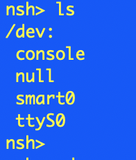
  • Check the drive appears in /dev
  • Ensure the drive has been mounted correctly in/mnt
  • Check that the clusteruser can create files and directories

Starting a ssh session on the Raspberry Pi we can manually check the system:

Linux TestServer500 6.6.31+rpt-rpi-2712 #1 SMP PREEMPT Debian 1:6.6.31-1+rpt1 (2024-05-29) aarch64

The programs included with the Debian GNU/Linux system are free software;
the exact distribution terms for each program are described in the
individual files in /usr/share/doc/*/copyright.

Debian GNU/Linux comes with ABSOLUTELY NO WARRANTY, to the extent
permitted by applicable law.
Last login: Sun Jun 30 10:15:00 2024 from fe80::1013:a383:fe75:54e6%eth0
clusteruser@TestServer500:~ $ df -h
Filesystem      Size  Used Avail Use% Mounted on
udev            3.8G     0  3.8G   0% /dev
tmpfs           806M  5.3M  800M   1% /run
/dev/sda2       229G  2.3G  215G   2% /
tmpfs           4.0G     0  4.0G   0% /dev/shm
tmpfs           5.0M   48K  5.0M   1% /run/lock
/dev/nvme0n1    469G   28K  445G   1% /mnt/nvme0
/dev/sda1       510M   64M  447M  13% /boot/firmware
tmpfs           806M     0  806M   0% /run/user/1000
clusteruser@TestServer500:~ $ cd /mnt
clusteruser@TestServer500:/mnt $ ls -l
total 4
drwxr-xr-x 3 clusteruser clusteruser 4096 Jun 30 10:14 nvme0
clusteruser@TestServer500:/mnt $ cd nvme0
clusteruser@TestServer500:/mnt/nvme0 $ mkdir Test
clusteruser@TestServer500:/mnt/nvme0 $ echo "Hello, world" > hello.txt
clusteruser@TestServer500:/mnt/nvme0 $ cat < hello.txt
Hello, world
clusteruser@TestServer500:/mnt/nvme0 $ ls -l
total 24
-rw-r--r-- 1 clusteruser clusteruser    13 Jun 30 10:16 hello.txt
drwx------ 2 clusteruser clusteruser 16384 Jun 30 10:14 lost+found
drwxr-xr-x 2 clusteruser clusteruser  4096 Jun 30 10:15 Test

Looking good.

Lesson Learned

There were a few things that caused issues along the way.

Raspberry Pi – Access Denied

As mentioned in Step 2 – Ensure SSH Works, we need to log in to the Raspberry Pi in order for Ansible to be able to connect to the Raspberry Pi and run the playbook. Missing the first step, logging on to the Raspberry Pi will result in the following error:

TASK [Gathering Facts] ******************************************************************************************************************************
fatal: [testserver500.local]: FAILED! => {"msg": "Using a SSH password instead of a key is not possible because Host Key checking is enabled and sshpass does not support this.  Please add this host's fingerprint to your known_hosts file to manage this host."}

Missing the second step, copying the SSH ID will result in the following error:

TASK [Gathering Facts] ******************************************************************************************************************************
fatal: [testserver500.local]: UNREACHABLE! => {"changed": false, "msg": "Invalid/incorrect password: Permission denied, please try again.", "unreachable": true}

Permission Denied

In the Step 4 – Format and Configure the Drives script we have the following:

- name: Mount the newly formatted drive
  command: mount /dev/nvme0n1 /mnt/nvme0

- name: Make sure that the user can read and write to the mount point
  command: chown -R {{ ansible_user }}:{{ ansible_user }} /mnt/nvme0

Switching these two lines result in the user not being able to write to the file system on the /mnt/nvme0 drive. Read and execute access are allowed but write access is denied.

Conclusion

The scripts presented here allow for a new Raspberry Pi to be configured with a newly formatted NVMe SSD drive in only a few minutes. This method does present a small issue in that the NVMe drive will be formatted as part of the set up process which does mean that the data on the drive will be lost. Something that is easy to resolve.

Repeatable Deployments Part 2 – NVMe Base

Monday, June 24th, 2024

NVMe Base on Raspberry Pi

A while ago, I started a series about creating Repeatable Deployments documenting the first step of the process, namely getting an OS onto a Raspberry Pi equipped with a USB SSD drive.

In this post we will look at the steps required to install a NVMe SSD into the environment and automate configuring the system. At the end of the post we should have two drives installed:

  • USB SSD drive holding the operating system and any applications used
  • NVMe drive for holding persistent data

The first of these drives will be considered transient with the operating system and applications changing but always installed in a repeatable manner. The second drive will be used to hold data which should persist even if the operating system changes.

The Hardware

The release of the Raspberry Pi 5 gave us supported access to the high speed PCIe and this means we have the option to install SSD drives using PCIe to give high speed disc access to the Raspberry Pi. A number of manufacturers have developed boards to support the addition of PCIe devices from SSD (which we will look at) to AI coprocessor boards.

There have been a number of reports concerning the compatibility of various drives and the boards offering access to the PCIe bus on the Raspberry Pi. For this reason I decided to use the a board that is supplied with a known working SSD. Luckily Pimoroni has two boards on offer that can be purchased stand alone or with a known working SSD:

For this post we will look at the single drive option with a 500GB SSD.

As usual with Pimoroni, ordering was easy and delivery was quick with the unit arriving the next day.

Pimoroni also provide a list of alternative known working drives along with some that may work. This list ocan be found on the corresponding produce page (links above). There is also a link to the Pi Benchmarks site that provides speed information for the various drives.

Assembly

Following the assembly guide was fairly painless. The most difficult step was to install the flat flex connector between the NVMe Base and the Raspberry Pi 5.

Configuration

The product page for the NVMe Base contains a good installation guide. This guide assumes that the SSD installed on the NVMe base is going to be used as the main boot drive for the system and that the OS etc. will be copied from existing bootable media. This is not the case for this installation.

System Update

As with all Pi setups, the first thing we should do is make sure that we have the most recent OS and software.

sudo apt get update -y
sudo apt get dist-upgrade -y
sudo reboot now

This should ensure that we have the latest and greatest deployed to the board.

Firmware Update and Setting the PCIe Mode

The first two steps are common to both the bootable scenario and this scenario. The firmware will need to be checked and if necessary updated and then experimental PCIe mode enabled.

Firstly, choose the boot ROM version and set this to the latest and reboot the system. The following command will configure the system to use the latest boot ROM.

sudo raspi-config nonint do_boot_rom E1 1
sudo reboot now

Further information on using the raspi-config tool in command mode can be found in the Raspi-Config documentation. Note however, that at the time of writing the documentation was slightly out of date as there was no mention of the need for the number 1 at the end of the command. This is required to answer No to the question about resetting the bootloader to the default configuration.

Next up, check the bootloader version and update this if necessary by using the rpi-eeprom-update command:

sudo rpi-eeprom-update

This generated the following output:

BOOTLOADER: up to date
   CURRENT: Fri 16 Feb 15:28:41 UTC 2024 (1708097321)
    LATEST: Fri 16 Feb 15:28:41 UTC 2024 (1708097321)
   RELEASE: latest (/lib/firmware/raspberrypi/bootloader-2712/latest)
            Use raspi-config to change the release.

PCIe Experimental Mode (Optional)

The last step is optional and turns on an experimental high speed feature, namely PCIe mode 3. Edit the /boot/firmware/config.txt file and add the following to the end of the file:

[all]
dtparam=pciex1_gen=3

This step is optional and without this entry the system will run in PCIe mode 2.

Reboot

So the boot loader is up to date, time for another reboot using the command sudo reboot now.

Mounting the Drive

We should now be at the point where the system has the correct configuration to allow access to the drive mounted to the NVMe Base. These drives should be in the /dev directory:

ls /dev/nv*

shows:

/dev/nvme0  /dev/nvme0n1

This looks good, as the drive shows up as the two devices. Now we need to put a file system on the drive, the following formats the drive using the ext4 file system:

sudo mkfs.ext4 /dev/nvme0n1 -L Data

For the 500GB ADATA drive supplied with the NVMe Base kit, this command generates the following:

mke2fs 1.47.0 (5-Feb-2023)
Discarding device blocks: done
Creating filesystem with 125026900 4k blocks and 31260672 inodes
Filesystem UUID: 008efe62-93f2-4875-bf52-5843953db8d0
Superblock backups stored on blocks:
	32768, 98304, 163840, 229376, 294912, 819200, 884736, 1605632, 2654208,
	4096000, 7962624, 11239424, 20480000, 23887872, 71663616, 78675968,
	102400000

Allocating group tables: done
Writing inode tables: done
Creating journal (262144 blocks): done
Writing superblocks and filesystem accounting information: done

Next up we need to mount the file system and make it accessible to the user. Assuming the default (current) user is pi and the user is in the group pi then the following commands will make the drive available to the current session:

sudo mkdir /mnt/nvme0
sudo chown -R pi:pi /mnt/nvme0
sudo mount /dev/nvme0n1 /mnt/nvme0

Firstly, we make the mount point for the partition and then ensure that the pi user has access to the mount point. Finally we mount the partition /dev/nvme0n1 as /mnt/nvme0. The availability of the drive can be checked with the df command, running:

df -h

should result in something like:

Filesystem      Size  Used Avail Use% Mounted on
udev            3.8G     0  3.8G   0% /dev
tmpfs           806M  5.2M  801M   1% /run
/dev/sda2       229G  1.8G  216G   1% /
tmpfs           4.0G     0  4.0G   0% /dev/shm
tmpfs           5.0M   48K  5.0M   1% /run/lock
/dev/sda1       510M   63M  448M  13% /boot/firmware
tmpfs           806M     0  806M   0% /run/user/1000
/dev/nvme0n1    469G   28K  445G   1% /mnt/nvme0

Access should now be checked by copying some files or creating a directory on the drive.

Mounting the Partition Automatically

The final step to take is to mount the partition and make the file system available as soon as the system boots. If the Raspberry Pi is rebooted now and the df -h command is run then something like the following is shown:

Filesystem      Size  Used Avail Use% Mounted on
udev            3.8G     0  3.8G   0% /dev
tmpfs           806M  5.2M  801M   1% /run
/dev/sda2       229G  1.8G  216G   1% /
tmpfs           4.0G     0  4.0G   0% /dev/shm
tmpfs           5.0M   48K  5.0M   1% /run/lock
/dev/sda1       510M   63M  448M  13% /boot/firmware
tmpfs           806M     0  806M   0% /run/user/1000

Note that the drive /mnt/nvme0 has not appeared in the list of file systems available. Executing ls /dev/nvm* shows the device is available but it has not been mounted.

The first step in mounting the drive automatically is to find the unique identified (UUID) for the device using the command:

sudo blkid /dev/nvme0n1

This resulted in the following output:

/dev/nvme0n1: LABEL="Data" UUID="008efe62-93f2-4875-bf52-5843953db8d0" BLOCK_SIZE="4096" TYPE="ext4"

Make a note of the UUID shown for your drive. The final step is to add this to the /etc/fstab file, so edit this file with the command:

sudo nano /etc/fstab

and add the following line to the end of the file:

UUID=008efe62-93f2-4875-bf52-5843953db8d0 /mnt/usb1 ext4 defaults,auto,users,rw,nofail,noatime 0 0

Remember to substitute the UUID for the drive on your system for the UUID above.

Time for one final reboot of the system and log on to the Raspberry Pi. Check the availability of the file system with the df -h command. The drive should now be available and accessible to the pi user as well as any users in the pi group.

Conclusion

The NVMe Base boards offer a way to add M-key NVMe SSD drives to the Raspberry Pi using PCIe gen 2 and even experimental access using PCIe gen 3. This results in high speed access to data stored on these drives as well as increased reliability over SD card boot devices.

The standard installation documentation is excellent but it assumes that the NVMe Base is going to host the OS as well as user data on the drive installed on the NVMe base. It also makes the assumption that the user will be using the Raspberry Pi desktop and not running in a headless situation.

Hopefully the above shows how to install the NVMe Base and SSD drive as a data storage only media with a second drive acting as the OS boot device.

In the next post we will look at taking the above steps and automating them to allow for reliable, repeated installations.

Test Environments

Tuesday, May 28th, 2024

Pi v.s. Mac Mini

Not really a technical article this time, instead a review of setting up a test environment with Raspberry Pi v.s. a used Mac Mini.

The introduction of the Raspberry Pi has brought low cost computing to the market. These small machines can help set up test environments where high speed and resource hungry systems are not required. I have used these for many years to provide a self contained environment which can possibly allow a debugger to be attached to an embedded development board.

So why the Pi v.s. Mac Mini question?

Raspberry Pi 5

The increasing power of the Raspberry Pi small board computer has also been accompanied by an increasing cost for the boards. The latest model (at the time of writing) , the Pi 5, can cost over £80 plus shipping and this is for the Raspberry Pi alone. A number of other components are also required:

  • Power supply – £10
  • Storage – £10+ for SD card, more for SSD

The following optional components would also be recommended for a self contained test environment:

  • Active cooler – £5
  • Case – £10

Personally, I recommend using a SSD with a USB to SATA adapter as a minimum for storage as these drives tend to be faster and more reliable than SD cards.

Adding all of this together brings the base cost for a usable system that can be used as a test controller to around £140 including shipping (assuming a 256GB SSD).

Alternatives?

CEX is a chain of shops in the UK that buy and sell used electronic equipment. Any equipment sold by CEX has a 2 year warranty so there is some peace of mind about the quality of the goods being sold.

So why mention them?

As mentioned at the top of this article, the test test controller does not necessarily have to be very powerful. This means that a 3 (or more) year old machine will be more than capable of doing the job.

Enter the Intel range of Mac Mini computers. These can be picked up from as little as £80 for a low spec Intel edition with higher specification Intel machine available for around £150. These prices more than match those of a current Raspberry Pi 5 with the accessories needed to make the system useful. This is especially true when you consider that the Mac Mini comes with storage and power supply all built into the system.

Long Term Support

The Raspberry Pi Foundation has a history of long term support. The latests operating system release also include support for the original Raspberry Pi released over a decade ago. This is fairly impressive and something not matched by many (if any) other hardware vendors.

The Intel range of Mac Mini computers are fairly well supported but older hardware has ceased to be supported for new operating system releases. Security releases are still made available for older systems but new features are not.

So the question is does this really matter for an isolated tests system? Probably not but if software support is a concern then the Raspberry Pi is the better choice at this price point.

Conclusion

Modern software development requires the use of fairly powerful computers. This article is being written on a modern Mac laptop with a powerful M2 processor and 32 GB of RAM. This sort of power is needed for compilation but is overkill for execution and supervision of test environment for embedded development.

Using used equipment keeps them alive and prevents them going to recycling (at least for a few years) making them environmentally friendly and cost effective.

Repeatable Deployments (Part 1)

Tuesday, March 19th, 2024

Repeatable Deployment Banner

A common problem in the IT world is to create a consistent environment in a repeatable manner. This is important in a number of use cases:

  • Development
  • Testing
  • Training

This series of posts will investigate using Ansible to create a consistent test environment, one that can be setup and torn down quickly and easily.

The starting point is setting up the hardware and installing the operating system (OS) which will be covered here. Subsequent posts will use Ansible to configure the system and deploy additional tools.

The Hardware

The test environment will be based around the Raspberry Pi 5 (although any version of the Pi hardware could be used). The system will be built around the following components:

  • Raspberry Pi (3, 4 or 5)
  • 256 GByte SATA SSD
  • SATA to USB adapter
  • Cooling fan (for the Raspberry Pi 5)
  • Power Supply
  • Ethernet cable
  • 3D printed mounts to bring everything together

Grabbing a Raspberry Pi 5 and putting all of this together yields something like this:

Raspberry Pi Setup

Raspberry Pi Setup

SATA SSDs have been chosen for the OS and data storage as they are both faster and more reliable than SD cards. From a cost perspective they are not too much more expensive than a quality SD card. It should be noted that recent third party addon boards are becoming available that add one or two NVMe drives to be added to the the Raspberry Pi 5 using the PCIe bus.

Write OS Image

The easiest way to create a bootable Raspberry Pi system is to use the Raspberry Pi Imager. This is a free tool that allows the selection of one of the many operating systems available for the Raspberry Pi and it can then be used to write the operating system to a SD card or HDD/SSD

The process starts by connecting the SATA to USB adapter the the SSD and then connecting the drive to the host computer. This makes the drive appear as an external USB drive.

Now start Raspberry Pi Imager:

Raspberry Pi Imager

Raspberry Pi Imager

Select the device we are going to create the image for, in this case this is the Raspberry Pi 5:

Select Device

Select Device

The next step is to decide which operating system should be installed on the SSD. There are a large number of options and the selection will depend upon what you want to achieve. In this case we can use a basic system such as Raspberry Pi OS Lite. Firstly, select the Raspberry Pi (64-bit) operating system:

Select Operating System

Select Operating System

Now refine this selection and select the Raspberry Pi OS Lite (64-bit):

Select Raspberry Pi Lite

Select Raspberry Pi Lite

A basic system will be adequate as the device is intended to be run headless and so the desktop environment and applications are not required.

Next step is to select the storage device that the image will be written to. Once this is done we can move on to providing some configuration options for the operating system.

Ready For Configuration

Ready For Configuration

Click the Next button to move on to the next step, editing the configuration.

Edit Settings

Edit Settings

Clicking Edit setting starts the editing process. The General options are presented first, here we can set the following:

  • Hostname
  • User name and password
  • WiFi access point details
Customise General Settings

Customise General Settings

SSH should be enabled in order to run the system headless. This is enabled on the Services tab:

Customise Services

Customise Services

Clicking on Save now gives the option of applying the settings and start writing the image to the SSD:

Apply Settings

Apply Settings

The final step is to verify that the SSD can be erased:

Confirm Media Erase

Confirm Media Erase

Control now passes back to the main window where the write and verification progress can be monitored:

Writing OS

Writing OS

After a short while the the process will complete and Raspberry Pi Imager wil conform that the image has been written successfully and the drive can now be disconnected from the host computer and connected to the Raspberry Pi 5:

OS Write Successful

OS Write Successful

Conclusion

The whole process of creating the image is straightforward and only takes a few minutes. At the end of the process the Raspberry Pi is ready to boot.

The next step will be to start the installation and configuration of additional software tools and components. Something for the next post in this series.

Raspberry Pi Pico and Pico W Project Templates

Tuesday, September 5th, 2023

Pico Template Build Complete

There are somethings in software development that we do not do very often and because we perform the task infrequently we often forget the nuances (well I do). One of these tasks is creating a new project.

In this post we will look at one option for automating this process, GitHub Templates. This work is partially my own work but also a case of bringing together elements of other blog posts and GitHub repositories.

All of the code discussed below can be found in the PicoTemplate repository and this should be used as a reference throughout this post.

Starting a New Project

Several days ago, I was in the process of starting a new project for the Raspberry Pi Pico W using the picotool. For those who are not familiar with this tool is is meant to automate the project creation process for you. You simply tell the tool which features you are going to be using and a few other parameters like board type and it will generate a directory containing all of the necessary code and project files.

Sounds too good to be true. For me it was as no matter which feature list I requested I could not get an application to deploy to the board and talk to the desktop computer over UART or USB.

At this point I decided to take this back to basics and get Blinky up and running. The problem definition became:

  1. C++ application
  2. Blink the onboard LED
  3. Support both Pico and Pico W boards
  4. Standard IO output over UART or USB

It would also be desirable to automate as much of the process as possible.

Blinky

One complication with the Pico boards is that they both use a different mechanism to access the on board LED. The Pico has the LED wired directly to GPIO 25 whilst the Pico W uses a GPIO from the onboard WiFi / Bluetooth chip (hereafter referred to as just wireless). This means we have different versions of Blinky depending upon which board is selected. This also means that the Pico W board also needs an additional library to support the wireless chip even if we are not using any wireless features.

The simplest way of doing this is to use a template directory to contains the main application code and the project CMakeFileList.txt file for each board. We can then copy the template files for the appropriate board type into the sources directory.

Keeping with the theme of forgetting the nuances, we will add some scripts to perform some common tasks:

  1. Configure the system (copying the files to the correct locations)
  2. Build the application
  3. Flash a board using openocd

Our first task will be to set the system up with the correct main.cpp and CMakeFileList.txt files and put the files in the correct place. Checking the default CMakeFileList.txt file we see that the project is named projectname which is not very informative so the configuration script will also rename the project as well.

The purpose of the build script should be obvious, it will build the application code and also offer the ability to perform a full rebuild if necessary.

The final script will flash the board using openocd using another Raspberry Pi Pico configured as a debug probe. This was discussed a few weeks ago in the post PicoDebugger – Bringing Picoprobe and the PicoW Together. This set up also has the advantage of exposing the default UART to the host computer.

Using the Scripts

Using the scripts is a three step process, one of which is only really performed once.

The first step is to use the configure.sh script to copy the files and rename the project:

./configure.sh -b=picow -n=TestApplication

After running this command the src/main.cpp file will contain the code to blink the LED on a Pico W board and the project will have been renamed TestApplication.

Secondly, we can build the application using the build.sh script:

./build.sh

Finally, the application can be deployed to the board using the flash.sh script.

./flash.sh

The UF2 file (in the case above, TestApplication.uf2) can also be copied to the board if a debug probe is not available.

Scope Creep

The story was supposed to end here but this is not going to be the case.

There are some improvements that we can look at to make the system a little more comprehensive. These include:

  1. Add a testing framework
  2. Create a Docker file for build and testing

Both of these items are currently work in progress.

Acknowledgements

This project has been inspired by several others on github:

  • [Raspberry Pi Pico Examples](https://github.com/raspberrypi/pico-examples)
  • [Raspberry Pi Pico Template](https://github.com/cathiele/raspberrypi-pico-cpp-template)

Conclusion

The initial requirement of creating a template for Pico and Pico W development could have been achieved simply by creating two different templates, one for each board type. This would arguably have been quicker and less complex.

The addition of the testing framework and docker container into the requirement would have resulted in some duplication of work in each template. This made bringing the two templates together in one repository more logical as errors or additions in one project type are automatically part of the other board template.

PicoW with SmartFS

Sunday, July 2nd, 2023

Mounting SmartFS

One feature that I want to add to my current project is to add a small file system with files that have been built into the system at compile time. These files would then be available to the application at run time. Let’s look at how we can do can do this with NuttX.

This tutorial assumes that you have NuttX cloned and ready to build, if not then you can find out how to do this in the first article in this series.

Adding SmartFS to the Build

NuttX has a built in configuration for the PicoW with SmartFS already configured. The first thing we need to do is to start with a clean system and then configure the build to include NSH and the flash file system. Start by changing to the NuttX source directory and then executing the following commands:

make distclean
./tools/configure.sh -l raspberrypi-pico-w:nsh-flash

Now we have the system configured we can build the OS and applications by executing the following command:

make -j

This should take a minute or so on a modern machine. Now we can deploy the system to the PicoW either by using openocd or by dragging the uf2 file onto the PicoW drive. Now connect to the PicoW using a serial application and type help to show the menu of commands. You should see something like the following:

SmartFS Builtin Apps

SmartFS Builtin Apps

We can check to see if the SmartFS is available checking the contents of the /dev directory with the command ls /dev. This should result in something like the following if SmartFS has been enabled correctly:

Device Directory Listing

Device Directory Listing

We can mount the file system using the command mount -t smartfs /dev/smart0 /data and then check the contents of the /data directory and we should find one file in the directory, test. Checking the contents of the file with the command cat /data/test should find that it contains a single ine of text which should be Hello, world!.

So far, so good, we have built the system and proven that it contains the default file and correct contents.

Adding a New File to the System Image

The next piece of the puzzle is to work out how to add new files to the file system. This took a few hours to figure out, but here goes…

The first attempt lead me searching for RP2040_FLASH_FILE_SYSTEM in the source tree (ripgrep is a great tool for doing this). This lead to a number of possible files. Maybe we can narrow the search down a little.

Second attempt, let’s have a look for Hello, world!. This resulted in a smaller number of files leading to the file arch/arm/src/rp2040/rp2040_flash_initialize.S. This file is well documented and shows how to set up the SmartFS file system and at the end of the file it shows how to create an entry for the file we see when we list the mounted directory. Scrolling down to the end of the fie we find the following:

    sector      3, dir
    file_entry  0777, 4, 0, "test"

    sector      4, file, used=14
    .ascii      "Hello, world!\n"

    .balign     4096, 0xff
    .global     rp2040_smart_flash_end
rp2040_smart_flash_end:

This looks remarkably familiar. So what happens if we change the above to look like this:

    sector      3, dir
    file_entry  0777, 4, 0, "test"
    file_entry  0777, 5, 0, "test2"

    sector      4, file, used=14
    .ascii      "Hello, world!\n"

    sector      5, file, used=14
    .ascii      "Testing 1 2 3\n"

    .balign     4096, 0xff
    .global     rp2040_smart_flash_end
rp2040_smart_flash_end:

Building the system, deploying the code and executing the following commands:

mount -t smartfs /dev/smart0 /data
cd /data
ls

results in the following:

New file added to SmartFS

New file added to SmartFS

If we execute the command cat test2 we are rewarded with the output Testing 1 2 3.

Further testing shows that the file system survives through a reset. We can do the following:

  • echo “My test” > test3
  • rm test
  • reboot

These commands should remove the file test, create a new file test3 and then reboot the system. Checking the file system contents shows that the system persists the changes through a reset.

Conclusion

This experiment was a partial success. A simple file system has been made available to an application and the file system survives a reset. One issue remains, adding new files is a little complex. It also requires changes to the NuttX source tree outside of the applications folder. This could result in changes being lost when a new version of NuttX is released.

There could be a solution, ROMFS, stay tuned for the next episode.

VSCode Debugging with NuttX and Raspberry Pi PicoW

Wednesday, June 14th, 2023

VS Code Halted in NuttX __start

In the previous post, we managed to get GDB working with NuttX running on the Raspberry Pi PicoW. In this post we will look at using VSCode to debug NuttX.

For a large part of this post it was case of following Shawn Hymels guide Raspberry Pi Pico and RP2040 – C/C++ Part 2 Debugging with VS Code. This is an excellent guide and I recommend using it as a companion to this post.

We will start with the assumption that you have followed the previous post in this series and have a working NuttX build for the Raspberry Pi PicoW. We will also assume that you have a working VSCode installation with the Cortex-Debug extension installed.

Configuration Files

We will need to create (or modify) three configuration files to allow VSCode to debug NuttX.

  • launch.json
  • tasks.json
  • settings.json

In the first article of this series we created the directory NuttX-PicoW to hold the apps and nuttx folders holding out NuttX code. This directory is the project directory or in VS Code parlance, the workspaceFolder. The workspaceFolder should also contain the Raspberry Pi PicoW SDK and the Raspberry Pi specific version of openocd.

We now add a .vscode directory to the workspaceFolder. This directory will hold the three configuration files listed above.

Start by opening VS Code and opening the workspaceFolder. This should show the four folders already in the workspaceFolder. Now create a .vscode directory in the workspaceFolder if it does not already exist.

setting.json

Only one entry is required in the settings.json file and this is the location of the openocd executable. If you have followed these posts so far this will be in the openocd/src folder. Create a setting.json file in the .vscode folder and add the following to the file.

{
    "cortex-debug.openocdPath": "${workspaceFolder}/openocd/src/openocd"
}

Note that the name of the executable may vary depending upon your operating system this post is being written from a MacOS perspective.

tasks.json

The tasks.json file holds the entry that will be used to build NuttX prior to deployment. In Shawns document the projects being worked on use the cmake system. We need to modify this to build NuttX using make. We want VS Code to use the command make -C ${workspaceFolder}/nuttx -j to build NuttX. The build task below will create a task Build NuttX to do just this:

{
    "version": "2.0.0",
    "tasks": [
        {
          "label": "Build NuttX",
          "type": "cppbuild",
          "command": "make",
          "args": [
            "-C",
            "${workspaceFolder}/nuttx",
            "-j"
          ]
        }
      ]  
}

launch.json

Of the three files we are creating, the launch.json file is the most complex. Much of the file remains the same as that presented by Shawn but there are some differences. The file used here looks like this:

{
    "version": "0.2.0",
    "configurations": [
        {
            "name": "Pico Debug",
            "cwd": "${workspaceRoot}",
            "executable": "${workspaceFolder}/nuttx/nuttx.elf",
            "request": "launch",
            "type": "cortex-debug",
            "servertype": "openocd",
            "gdbPath" : "arm-none-eabi-gdb",
            "device": "RP2040",
            "configFiles": [
                "interface/cmsis-dap.cfg",
                "target/rp2040.cfg"
            ],
            "svdFile": "${workspaceFolder}/pico-sdk/src/rp2040/hardware_regs/rp2040.svd",
            "runToEntryPoint": "__start",
            "searchDir": ["${workspaceFolder}/openocd/tcl"],
            "openOCDLaunchCommands": ["adapter speed 5000"],
            "preLaunchTask": "Build NuttX"
        }
    ]
}

The following items are the ones that need to be changed:

“executable”: “${workspaceFolder}/nuttx/nuttx.elf”

This is the path to the executable that will be created by the build system. In this cse it is the NuttX ELF file. This may need to be changed to “executable”: “${workspaceFolder}/nuttx/nuttx” depending upon the output of the build system, this may simply be nuttx.

“configFiles”

The recent versions of the picoprobe software use a different interface to talk to the picoprobe. For versions 1.01 and above of the picoprobe software this interface changed from picoprobe.cfg to cmsis-dap.cfg.

“svdFile”: “${workspaceFolder}/pico-sdk/src/rp2040/hardware_regs/rp2040.svd”

We have a version of the Pico SDK specifically for our build requirements and so for this reason the location of the file is changed to reference the workspaceFolder rather than the global PICO_SDK_PATH environment variable.

“runToEntryPoint”: “__start”

This entry replaces the “runToMain”: true entry. Unlike convention C/C++ applications, NuttX does not have a main method. Having the runToMain entry generates an error stating that main cannot be found and stops at the first executable statement in our code, namely in __start. Replacing runToMain with runToEntryPoint achieves the same thing but does not generate the error.

Doing this also removes the need to have the postRestartCommands specified.

“searchDir”: [“${workspaceFolder}/openocd/tcl”]

This entry is used by openocd to look for the interface and target configuration files specified in the configFiles entry.

“openOCDLaunchCommands”: [“adapter speed 5000”]

These commands are executed by openocd when it starts. The change to the adapter speed is required and is documented in Getting Started with Raspberry Pi Pico documentation from the Raspberry Pi Foundation.

“preLaunchTask”: “Build NuttX”

The final entry tells Cortex-Debug how to build NuttX. It references the task we previously defined in the tasks.json file.

Testing

Testing this should simply be a case of saving all of the files above and pressing F5 in VS Code. If the changes have been successful then VS Code will first try to build NuttX in a Terminal window and it will then deploy NuttX to the Pico board and start the debugger. VS Code should look something like this (click on image for full view):

Debugging PicoW with VSCode

Debugging PicoW with VSCode

The inclusion of the SVD file allows us to examine the PicoW peripheral registers as well as the core registers:

PicoW Peripheral Registers in VSCode

PicoW Peripheral Registers in VSCode

Pico Cortex Registers in VSCode

Pico Cortex Registers in VSCode

Conclusion

GDB is a great debugger but it is often more convenient to use an IDE to debug your code. VS Code with the Cortex-Debug extension allow visual debugging of NuttX with a few nice additional features thrown in:

  • Easily viewed call stacks for both cores.
  • The SVD file allows the peripheral registers to be viewed through VS Code

We should also note that the use of VS Code resolved the issues noted at the end of the previous post as Cortex-Debug is able to deploy a binary using the picoprobe without resorting to the UF2 method of deployment. This results in a seamless build, deploy and debug process.

We have two debug options and it is now down to personal preferences as to which one to use.

Debugging NuttX on the Raspberry Pi Pico

Sunday, June 11th, 2023

GDB showing thread information

At some point in the development lifecycle we will hit some unexpected application behaviour. At this point we reach for the debugger to allow us to connect to the application an interrogate the state and hopefully we will be able to determine the cause of the problem. Working with NuttX is no different from any other application. The only complication we have is connecting to application running on the PicoW requires a debug adapter. Luckily, the Raspberry Pi Foundation has an affordable solution to this problem.

Environment

The getting started guide for the Pico has instructions on how to set up the environment for Linux, Mac and Windows. This post will be following the guide for MacOS adding some hardware to allow for a stable connection between the debug probe and the PicoW.

There are two options for the debug probe:

  • The Raspberry Pi debug probe
  • Use a Pico programmed as a debug probe

I have a number of Pico and PicoW boards and so the later option, using a Pico programmed as a debug probe, is going to be the most cost effective and this is the route we will look at here.

Hardware

For the purpose of discussion we will use the following terms to describe the two boards:

  • Picoprobe – Pico that is programmed to be a debug probe
  • Target – PicoW that is running the application we wish to debug

The getting stared guide shows how two Pico boards should be connected to provide both debugging and serial console output through a UART on the target board. This shows the two boards on a breadboard setup (image is taken from the Raspberry Pi Pico getting started guide under CC-BY-ND license).

Picoprobe and Pico Fritzing

Picoprobe and Pico Fritzing

The same setup can be reproduced on protoboard. This will make the setup a little more robust and permanent. Breaking out the soldering iron and the parts bin yielded the following:

Pico on Protoboard

Pico on Protoboard

The flying leads are needed to connect to the SWD debug headers on the PicoW as it was not possible to connect these through to the protoboard. The black (GND) and red (5V) wires provide power to the target board. This means that we only have one connector to the system, namely to the Picoprobe but we must take care not to exceed the power capabilities of the USB connection.

The white (SWCLK) and blue (SWDIO) flying leads provide the debug connection between the two boards. As with the permanent connections above, the black lead is a GND connection.

The blue and yellow leads connected permanently to the protoboard connect the UART from the target board through to the picoprobe. The picoprobe will use the USB connection to present the host computer with a connection through to the UART on the target board.

Software

The first piece of software needed is the Picoprobe software itself. There are instruction on how to build this but I found the simplest thing to do was to download the latest release from the Picoprobe GitHub repository. At the time of writing this is version 1.0.2. The Picoprobe software is deployed to the Pico being used as a Picoprobe in the usual way, reset the Pico whilst hold the BootSel button and then drag and drop the firmware file onto the drive present to the host computer.

The next thing we need is a version of openocd that can talk to the Picoprobe. The machine I am using is used to develop software for multiple boards and so the preferable solution is to build the Raspberry Pi Pico version of openocd for this setup and then reference this locally rather than install the software globally. This is the same approach taken for the various development environment I use to prevent them interfering with each other.

Following the guide (for Mac) we need to execute the following commands:

cd ~/pico
git clone https://github.com/raspberrypi/openocd.git --branch picoprobe --depth=1 $ cd openocd
export PATH="/usr/local/opt/texinfo/bin:$PATH" 1
./bootstrap
./configure --enable-picoprobe --disable-werror 2
make -j4

Check the latest version of the guide for instructions for your OS.

Now to try openocd… This is where I hit a problem caused by having out of date documentation. Following the latest documentation we need to execute the following command:

src/openocd -f interface/cmsis-dap.cfg -f target/rp2040.cfg -c "adapter speed 5000" -s tcl

I was following I hit two errors due to the out of date documentation:

  • Error: Can’t find a picoprobe device! Please check device connections and permissions.
  • Error: CMSIS-DAP command CMD_DAP_SWJ_CLOCK failed.

Both of these errors were corrected by using the command above to connect to the debug probe. Moral of the story, make sure you are using the latest information. If everything goes well then we should be rewarded with something similar to the following output:

Open On-Chip Debugger 0.11.0-g4f2ae61 (2023-06-10-18:20)
Licensed under GNU GPL v2
For bug reports, read
	http://openocd.org/doc/doxygen/bugs.html
Info : auto-selecting first available session transport "swd". To override use 'transport select <transport>'.
Info : Hardware thread awareness created
Info : RP2040 Flash Bank Command
adapter speed: 5000 kHz

Info : Listening on port 6666 for tcl connections
Info : Listening on port 4444 for telnet connections
Info : Using CMSIS-DAPv2 interface with VID:PID=0x2e8a:0x000c, serial=E66058388356A232
Info : CMSIS-DAP: SWD  Supported
Info : CMSIS-DAP: FW Version = 2.0.0
Info : CMSIS-DAP: Interface Initialised (SWD)
Info : SWCLK/TCK = 0 SWDIO/TMS = 0 TDI = 0 TDO = 0 nTRST = 0 nRESET = 0
Info : CMSIS-DAP: Interface ready
Info : clock speed 5000 kHz
Info : SWD DPIDR 0x0bc12477
Info : SWD DLPIDR 0x00000001
Info : SWD DPIDR 0x0bc12477
Info : SWD DLPIDR 0x10000001
Info : rp2040.core0: hardware has 4 breakpoints, 2 watchpoints
Info : rp2040.core1: hardware has 4 breakpoints, 2 watchpoints
Info : starting gdb server for rp2040.core0 on 3333
Info : Listening on port 3333 for gdb connections

If we have got here then we have the the debug probe programmed and we have a copy of openocd that can communicate with the picoprobe.

Reconfiguring NuttX

In previous posts we used UART over USB to communicate with the host computer. The picoprobe gives us another option, using the UART on the target board which is routed through the picoprobe. We must reconfigure NuttX in order to take advantage of the UART redirection. The configuration we want is raspberrypi-pico-w:nsh, so following the first post in this series and making the change to the configuration we need to execute the following:

make distclean
./tools/configure.sh -l raspberrypi-PicoW:nsh
make -j

At the end of this process we should have a new nuttx.uf2 file configured to use the UART port on the target board to communicate with the NuttX shell. This UF2 file can be deployed using the usual deployment process (Bootsel and reset followed by drag and dropping the file) to the target board.

At this point we should have two Pico boards programmed, one to be the picoprobe and one to be the target board (with NuttX). Now we can connect the boards (in my case using the protoboard shown above) and verify that NuttX is active and communicating through the UART.

Plugging the Pico (picoprobe) and the PicoW (target board) into the protoboard and then connecting the host computer to the picoprobe through USB presents the computer with a new serial port, usbmodem14302. Connecting to this port and hitting enter shows the nsh prompt. Asking for help shows the expected output.

nsh> help
help usage:  help [-v] [<cmd>]

    .         cat       df        free      mount     rmdir     truncate  
    [         cd        dmesg     help      mv        set       uname     
    ?         cp        echo      hexdump   printf    sleep     umount    
    alias     cmp       env       kill      ps        source    unset     
    unalias   dirname   exec      ls        pwd       test      uptime    
    basename  date      exit      mkdir     reboot    time      usleep    
    break     dd        false     mkrd      rm        true      xd        

Builtin Apps:
    nsh  sh   
nsh>

So we have a good UART connection and openocd can connect to the picoprobe.

Now we need to connect the debugger to openocd.

Debugging

To debug the board we will start with GDB, specifically arm-none-eabi-gdb-py as this has Python scripting enabled. We can use the scripting engine to automate some tasks later.

First thing to do is add a .gdbinit file to the directory we will be executing GDB from, in this case we will use the nuttx directory. The following commands should setup GDB and openocd ready for debugging. The nuttx ELF file will be loaded for us so by the time the GDB prompt is show we will have the symbol file loaded. Our .gdbinit file should look something like this:

set history save on
set history size unlimited
set history remove-duplicates unlimited
set history filename ~/.gdb_history

set output-radix 16
set mem inaccessible-by-default off

set remote hardware-breakpoint-limit 4
set remote hardware-watchpoint-limit 2

set confirm off

file nuttx
add-symbol-file -readnow nuttx

target extended-remote :3333
mon gdb_breakpoint_override hard

To debug we will need two terminal sessions open. In the first session run openocd as described above. In the second session start GDB (simply enter the command arm-none-eabi-gdb-py in the terminal session) making sure that you are in the directory containing the nuttx file and the .gdbinit file. If you are successful then you will see something like this:

GNU gdb (GDB) 13.1
Copyright (C) 2023 Free Software Foundation, Inc.
License GPLv3+: GNU GPL version 3 or later <http://gnu.org/licenses/gpl.html>
This is free software: you are free to change and redistribute it.
There is NO WARRANTY, to the extent permitted by law.
Type "show copying" and "show warranty" for details.
This GDB was configured as "x86_64-apple-darwin22.3.0".
Type "show configuration" for configuration details.
For bug reporting instructions, please see:
<https://www.gnu.org/software/gdb/bugs/>.
Find the GDB manual and other documentation resources online at:
    <http://www.gnu.org/software/gdb/documentation/>.

For help, type "help".
Type "apropos word" to search for commands related to "word".
add symbol table from file "../nuttx/nuttx"

We can now start to debug the application on the board. A few simple tests, firstly, reset the board with the GDB command mon reset halt. We should see something like this:

target halted due to debug-request, current mode: Thread
xPSR: 0xf1000000 pc: 0x000000ea msp: 0x20041f00
target halted due to debug-request, current mode: Thread
xPSR: 0xf1000000 pc: 0x000000ea msp: 0x20041f00

We can now set a breakpoint, say in nsh_main (b nsh_main) and run the application to the breakpoint (c). If we then ask for information about the threads (info thre) we should see something like this:

  Id   Target Id                                           Frame
* 1    Thread 1 (Name: rp2040.core0, state: breakpoint)    nsh_main (argc=0x1, argv=0x20003170) at nsh_main.c:58
  2    Thread 2 (Name: rp2040.core1, state: debug-request) 0x000000ea in ?? ()

Conclusion

Getting debugging up and running took a little more effort than I expected but was not expensive due to the ability to use a Pico to debug a Pico. There is some excellent debugger documentation on the NuttX web site. This suggests that openocd should support NuttX however I was not able to get this working with the Raspberry Pi release of openocd. It was a question of having Pico support or NuttX support. I’m going with the Pico support for the minute.

I was hoping to use the picoprobe board to deploy the application meaning that we only have one connection between the host computer and the development hardware. A little more research is going to be necessary to see if this can be done.

Adding SMP to NuttX on the Raspberry Pi PicoW

Tuesday, June 6th, 2023

ps Command Results without SMP Enabled

So far in this series we have configured NuttX to build C++ applications on the PicoW and we have created our own custom application and successfully deployed this to the board.

In this post we will look at configuring the system to use both cores on the RP2040 processor using the configuration we have developed over the previous posts. NuttX includes a SMP configuration already, raspberrypi-pico-w:smp, this uses UART0 for communication rather than USB hence we will look at add this configuration on top of the USB configuration.

Default Configuration

It appears that the default configuration for NuttX running on the PicoW is to run the processor as a single core processor. Running the ps in the NuttX shell yields the following output:

   PID GROUP PRI POLICY   TYPE    NPX STATE    EVENT     SIGMASK           STACK COMMAND
    0     0   0 FIFO     Kthread N-- Ready              0000000000000000 001000 Idle Task
    1     1 100 RR       Task    --- Running            0000000000000000 002000 nsh_main   

From the output we see that there are only two tasks running on the system. From this we can deduce that only one of the cores is enabled. If both cores were running then we should see two Idle Tasks running, one on each core plus the nsh_main task. This is confirmed in the SMP Documentation where we find the statement:

Each CPU will have its own IDLE task.

Now we have this confirmed, let’s move on to reconfiguring the system.

Enabling SMP

According to the documentation we need set three options through the configuration system in order to turn on SMP:

  • CONFIG_SMP
  • CONFIG_SMP_NCPUS
  • CONFIG_IDLETHREAD_STACKSIZE

Starting the configuration system with the make menuconfig we are presented with the top level options screen:

NuttX configuration system

NuttX configuration system

This poses the question “How do I find CONFIG_SMP and the rest of the options?”. Luckily, kconfig has a search option, pressing the / key presents the user with a search dialog box:

Search dialog here.

Typing SMP and pressing return shows a number of results, some are relevant to use, some are not. The longer the search term the more accurate the results will be. In our case, searching for SMP yields a number of results that are irrelevant. However, the top result looks like it is the one for us:

SMP Search results image Here.

The results give us a fair amount of information about the configuration options. If we look at the top entry for SMP (this is actually the option that we need to turn on) the system is giving us the following information:

  • The option name (SMP) which will translate to CONFIG_SMP in the various include files
  • The location of the option, in this case RTOS Features -> Tasks and Scheduling
  • In which file (and the line number) the option is defined, sched/Kconfig, line 271
  • Any other options that this option depends upon.
  • Any options that will be turned on as a result of selecting this option

You will also note a number in brackets at the side of Tasks and Scheduling. This is the short cut key, in this case 1 and pressing 1 will take us to the appropriate place in the configuration system.

RTOS Features options.

Selecting Tasks and Scheduling by pressing enter we are presented with the following:

Tasks and scheduling, no SMP.

Notice that there is no option to turn on SMP. Confused, so was I the first time I saw this. Pressing the ESC key a few times should take us back to the search results. Reading these more carefully we note the following:

Depends on: ARCH_HAVE_MULTICPU [=y] && ARCH_HAVE_TESTSET [=y] && ARCH_INTERRUPTSTACK [=0]!=0

So we have to ensure that three conditions are met in order to enable SMP:

  • HAVE_MULTICPU is set to turned on, this looks to be the case (ARCH_HAVE_MULTICPU [=y])
  • HAVE_TESTSET is turned on, again this looks to be the case (ARCH_HAVE_TESTSET [=y])
  • INTERRUPTSTACK has a non-zero value, this appears to be false (ARCH_INTERRUPTSTACK [=0]!=0)

It appears that we have not met all of the conditions to activate SMP. We need to look at defining a size for the interrupt stack. So using the search system again but this time for ARCH_INTERRUPTSTACK we get the following results:

Interrupt stack search results

Pressing the 1 key takes us directory to the entry we need to change. Setting the value to 2048 should be a reasonable starting point. We can always adjust this later if we find it is causing problems.

Exiting this menu and the search for ARCH_INTERRUPTSTACK we can search for SMP again. Pressing the 1 key in the search results presents us with a different view, this time we are taken to the SMP option and we can now turn this on. If we do this the system will add some new entries to the menu, one of which defines the number of CPUs available and this is set to 4. We will need to change this value to 2.

SMP Configured image.

We are now ready to build the system.

Build and Deploy NuttX

We should now be ready to build and deploy the system to the PicoW. Executing the following command will build NuttX and create the UF2 file ready for deployment:

make clean
make -j

At the end of the build process we can deploy the UF2 file to the board by putting the board in bootloader mode and dropping the file to the drive that is shown on the host computer. Se the first article in this series for more information on how to do this.

Time to connect our serial terminal to the PicoW and run the ps command once again:

SMP Enabled ps output.

As you ca see from the screen shot above, we now have two ide tasks as expected and the ps command has some additional information, notably the CPU that each task is allocated to.

Conclusion

Adding SMP to the system was not as simple as it first sounded. The main lesson from this was to check the dependencies in the search results. The requirement for an interrupt stack was not discussed in the SMP documentation and this caused some confusion initially. The help in the configuration system came to our rescue and the situation was easily recoverable.

If you have been following the series we are now at the point where we have think about some serious development. We now have space for our own application code, C++ is enabled and we are able to use both cores on the RP2040 microcontroller.

At this point the series will slow down a little as some of the features now need some in depth investigation most notable:

  • Using SMP correctly in NuttX
  • Interprocess communication between tasks running on different cores
  • RP2040 PIO and NuttX

Adding a User Application to NuttX

Tuesday, June 6th, 2023

Enable SSEM User Application

So far we have seen how to deploy NuttX to a Raspberry Pi PicoW and enable C++ in NuttX. Next up we will create our own application and deploy it to the PicoW.

Creating a New Application

The build system for NuttX applications uses a a makefile that is written in such a way that all we have to do to add a new application is simply create a directory containing some template files. The easiest way to do this is to use an existing application as a template. So let us start by making a copy of the helloxx application. This can be found in the apps repository in the examples directory. So we will start by making a recursive copy of this directory and renaming it ssem.

Looking inside the ssem directory we find a number of files:

helloxx_main.cxx
Make.defs
Kconfig
Makefile

Time to start editing the files.

helloxx_main.cxx

We will start by renaming the file to represent the application name, so we will rename this to ssem_main.cxx. Now editing the file we change all occurrences of helloxx_main to ssem_main. This will allow us to verify that we have indeed deployed the application.

Makefile

Make a similar change to the Makefile by changing all occurrences of helloxx to ssem. Make changes to the comments to reflect that this application is a new application. Our Makefile should now look something like this:

include $(APPDIR)/Make.defs

# SSEM Application

MAINSRC = ssem_main.cxx

# ssem built-in application info

PROGNAME = ssem
PRIORITY = SCHED_PRIORITY_DEFAULT
STACKSIZE = $(CONFIG_DEFAULT_TASK_STACKSIZE)
MODULE = $(CONFIG_EXAMPLES_SSEM)

include $(APPDIR)/Application.mk

Make.defs

The Make.defs file conditionally adds the new application to the list of configured applications and ensures that the file will be built. This file should be edited to look something like this:

ifneq ($(CONFIG_EXAMPLES_SSEM),)
CONFIGURED_APPS += $(APPDIR)/examples/ssem
endif

Kconfig

The Kconfig file allows us to define and change application parameters, something we may look at later. For the moment it simply defines the application name and title and tells the configuration system how to turn compilation on or off. Making changes similar to the above we will have a file that contains something like this:

config EXAMPLES_SSEM
tristate "SSEM example"
default n
depends on HAVE_CXX
---help---
    Enable the SSEM application

Build the SSEM Application

Now we have set up the application we can start to reconfigure the build system and deploy the application. First thing to do is to clean the current build environment in order to make NuttX aware of the presence of the application. Issuing the command make clean will remove the previous build components.

Now we can configure the environment by issuing the make menuconfig command. This will present the configuration menuing system we saw in the previous post. So now head over to the following menu items and disable the Hello, world example and enable the SSEM example.

  • Main menu -> Application Configuration -> “Hello, World!” C++ example
  • Main menu -> Application Configuration -> SSEM example

We should now be ready to build the system, so execute the command make -j to build the system. The build system should show output similar to the following if the changes to the system have been made correctly:

Create version.h
LN: platform/board to /Projects/NuttX/apps/platform/dummy
Register: ssem
Register: nsh
Register: sh
CPP:  /Projects/NuttX/nuttx/boards/arm/rp2040/raspberrypi-pico-w/scripts/raspberrypi-pico-flash.ld-> /Projects/NuttX/nuttx/boards/arm/rp2040/raspberrypi-pico-w/scripts/raspberrypi-pico-flash.lLD: nuttx
Generating: nuttx.uf2
tools/rp2040/elf2uf2 nuttx nuttx.uf2;

Time to deploy NuttX to the board and check to see if the application has built correctly. So copy the NuttX.uf2 file to the board and connect a serial console to the serial port. Press enter a few times until the nsh prompt appears and now type help. The new application should appear in the list of built in applications:

Builtin Apps:
    nsh   sh    ssem  

Executing the ssem application should now present something similar to the following (depending upon how you modified the helloxx_main application code):


nsh> ssem
ssem_main: Saying hello from the dynamically constructed instance
CHelloWorld::HelloWorld: Hello, World!!
ssem_main: Saying hello from the instance constructed on the stack
CHelloWorld::HelloWorld: Hello, World!!
nsh>

Conclusion

The process of creating a new application and having this included in the NuttX build system is not a difficult task, it simply means editing a few files.

One key step is the make clean step as omitting this from a system which already contains build artefacts may not include the new application in the configuration process and hence exclude the files from the build.

In the next post we will add SMP to the configuration.