VSCode Debugging with NuttX and Raspberry Pi PicoW
Wednesday, June 14th, 2023

In the previous post, we managed to get GDB working with NuttX running on the Raspberry Pi PicoW. In this post we will look at using VSCode to debug NuttX.
For a large part of this post it was case of following Shawn Hymels guide Raspberry Pi Pico and RP2040 – C/C++ Part 2 Debugging with VS Code. This is an excellent guide and I recommend using it as a companion to this post.
We will start with the assumption that you have followed the previous post in this series and have a working NuttX build for the Raspberry Pi PicoW. We will also assume that you have a working VSCode installation with the Cortex-Debug extension installed.
Configuration Files
We will need to create (or modify) three configuration files to allow VSCode to debug NuttX.
- launch.json
- tasks.json
- settings.json
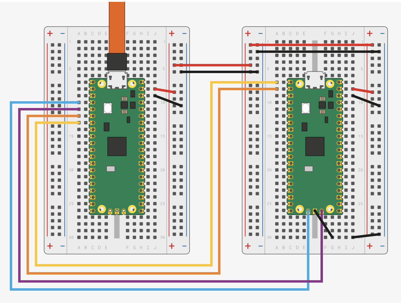
In the first article of this series we created the directory NuttX-PicoW to hold the apps and nuttx folders holding out NuttX code. This directory is the project directory or in VS Code parlance, the workspaceFolder. The workspaceFolder should also contain the Raspberry Pi PicoW SDK and the Raspberry Pi specific version of openocd.
We now add a .vscode directory to the workspaceFolder. This directory will hold the three configuration files listed above.
Start by opening VS Code and opening the workspaceFolder. This should show the four folders already in the workspaceFolder. Now create a .vscode directory in the workspaceFolder if it does not already exist.
setting.json
Only one entry is required in the settings.json file and this is the location of the openocd executable. If you have followed these posts so far this will be in the openocd/src folder. Create a setting.json file in the .vscode folder and add the following to the file.
{
    "cortex-debug.openocdPath": "${workspaceFolder}/openocd/src/openocd"
}
Note that the name of the executable may vary depending upon your operating system this post is being written from a MacOS perspective.
tasks.json
The tasks.json file holds the entry that will be used to build NuttX prior to deployment. In Shawns document the projects being worked on use the cmake system. We need to modify this to build NuttX using make. We want VS Code to use the command make -C ${workspaceFolder}/nuttx -j to build NuttX. The build task below will create a task Build NuttX to do just this:
{
    "version": "2.0.0",
    "tasks": [
        {
          "label": "Build NuttX",
          "type": "cppbuild",
          "command": "make",
          "args": [
            "-C",
            "${workspaceFolder}/nuttx",
            "-j"
          ]
        }
      ]
}
launch.json
Of the three files we are creating, the launch.json file is the most complex. Much of the file remains the same as that presented by Shawn but there are some differences. The file used here looks like this:
{
    "version": "0.2.0",
    "configurations": [
        {
            "name": "Pico Debug",
            "cwd": "${workspaceRoot}",
            "executable": "${workspaceFolder}/nuttx/nuttx.elf",
            "request": "launch",
            "type": "cortex-debug",
            "servertype": "openocd",
            "gdbPath" : "arm-none-eabi-gdb",
            "device": "RP2040",
            "configFiles": [
                "interface/cmsis-dap.cfg",
                "target/rp2040.cfg"
            ],
            "svdFile": "${workspaceFolder}/pico-sdk/src/rp2040/hardware_regs/rp2040.svd",
            "runToEntryPoint": "__start",
            "searchDir": ["${workspaceFolder}/openocd/tcl"],
            "openOCDLaunchCommands": ["adapter speed 5000"],
            "preLaunchTask": "Build NuttX"
        }
    ]
}
The following items are the ones that need to be changed:
“executable”: “${workspaceFolder}/nuttx/nuttx.elf”
This is the path to the executable that will be created by the build system. In this cse it is the NuttX ELF file. This may need to be changed to “executable”: “${workspaceFolder}/nuttx/nuttx” depending upon the output of the build system, this may simply be nuttx.
“configFiles”
The recent versions of the picoprobe software use a different interface to talk to the picoprobe. For versions 1.01 and above of the picoprobe software this interface changed from picoprobe.cfg to cmsis-dap.cfg.
“svdFile”: “${workspaceFolder}/pico-sdk/src/rp2040/hardware_regs/rp2040.svd”
We have a version of the Pico SDK specifically for our build requirements and so for this reason the location of the file is changed to reference the workspaceFolder rather than the global PICO_SDK_PATH environment variable.
“runToEntryPoint”: “__start”
This entry replaces the “runToMain”: true entry. Unlike convention C/C++ applications, NuttX does not have a main method. Having the runToMain entry generates an error stating that main cannot be found and stops at the first executable statement in our code, namely in __start. Replacing runToMain with runToEntryPoint achieves the same thing but does not generate the error.
Doing this also removes the need to have the postRestartCommands specified.
“searchDir”: [“${workspaceFolder}/openocd/tcl”]
This entry is used by openocd to look for the interface and target configuration files specified in the configFiles entry.
“openOCDLaunchCommands”: [“adapter speed 5000”]
These commands are executed by openocd when it starts. The change to the adapter speed is required and is documented in Getting Started with Raspberry Pi Pico documentation from the Raspberry Pi Foundation.
“preLaunchTask”: “Build NuttX”
The final entry tells Cortex-Debug how to build NuttX. It references the task we previously defined in the tasks.json file.
Testing
Testing this should simply be a case of saving all of the files above and pressing F5 in VS Code. If the changes have been successful then VS Code will first try to build NuttX in a Terminal window and it will then deploy NuttX to the Pico board and start the debugger. VS Code should look something like this (click on image for full view):
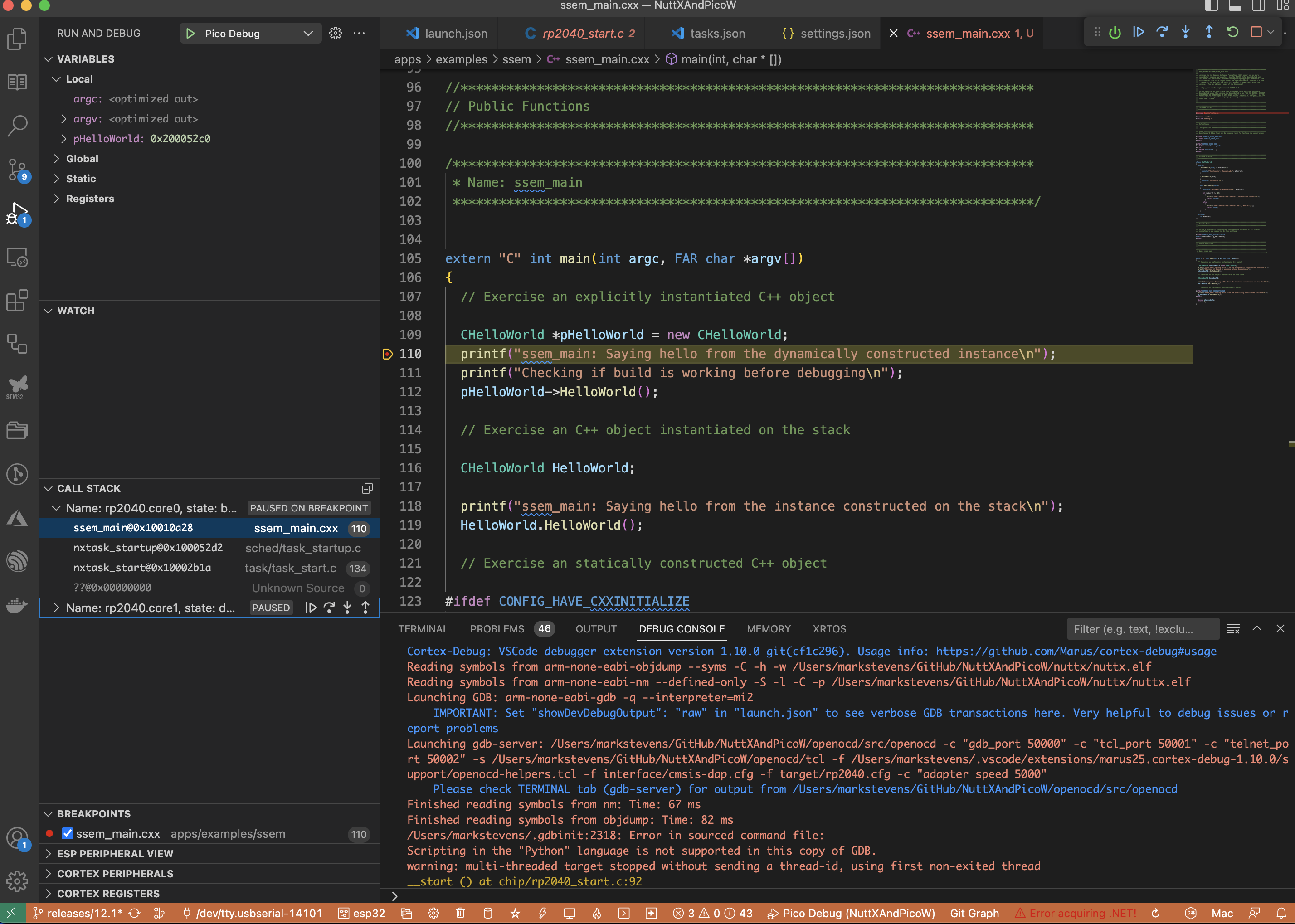
Debugging PicoW with VSCode
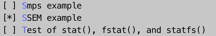
The inclusion of the SVD file allows us to examine the PicoW peripheral registers as well as the core registers:
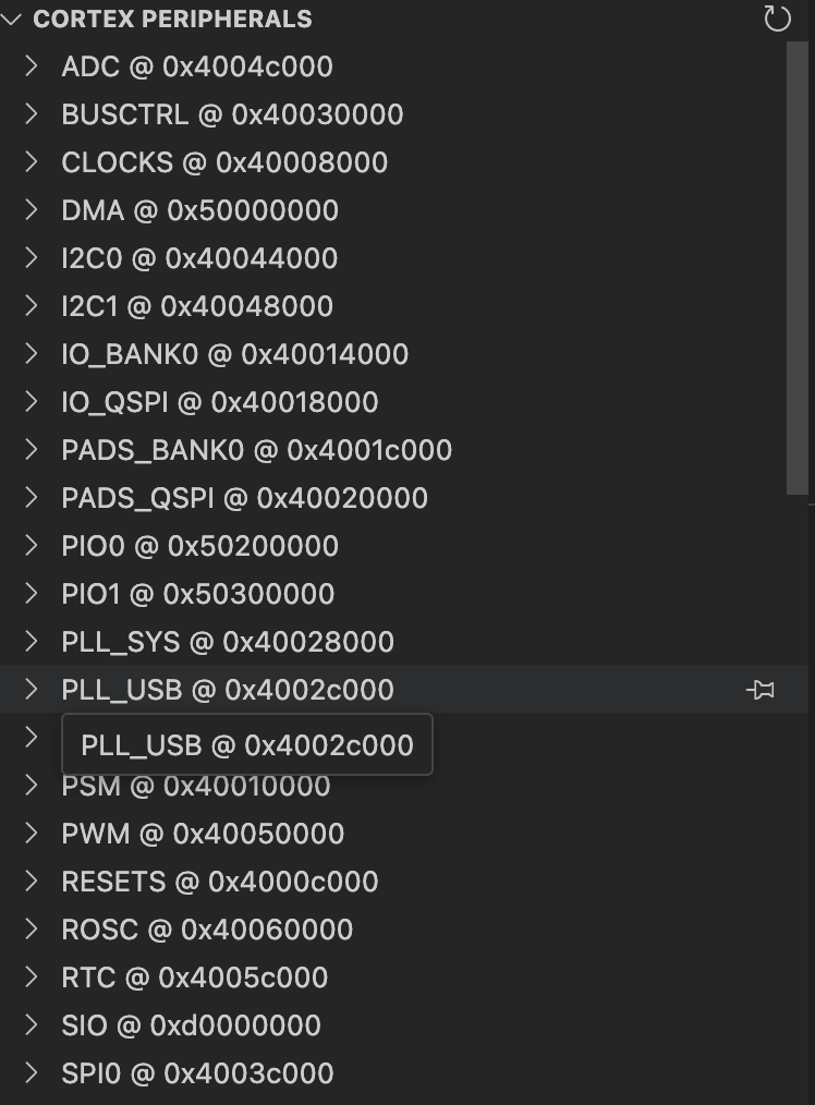 PicoW Peripheral Registers in VSCode |
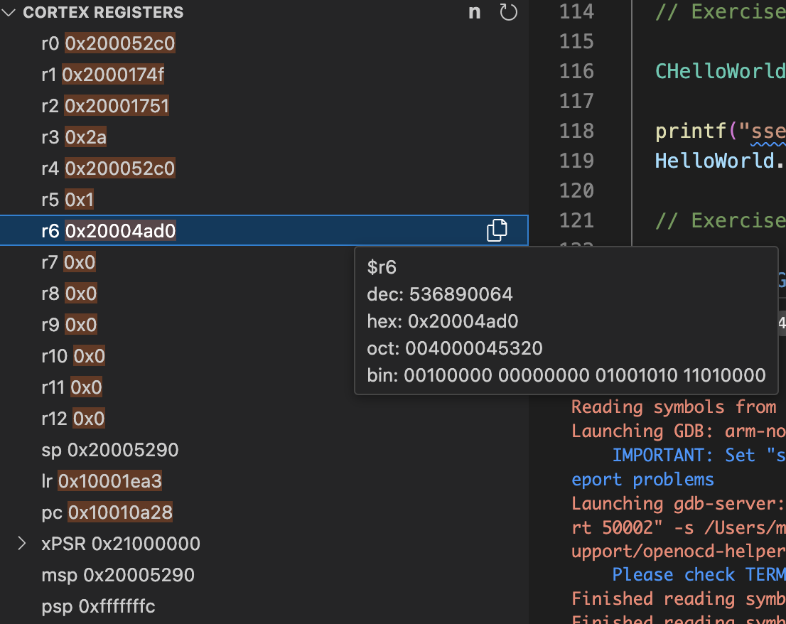 Pico Cortex Registers in VSCode |
|---|
Conclusion
GDB is a great debugger but it is often more convenient to use an IDE to debug your code. VS Code with the Cortex-Debug extension allow visual debugging of NuttX with a few nice additional features thrown in:
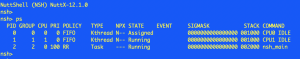
- Easily viewed call stacks for both cores.
- The SVD file allows the peripheral registers to be viewed through VS Code
We should also note that the use of VS Code resolved the issues noted at the end of the previous post as Cortex-Debug is able to deploy a binary using the picoprobe without resorting to the UF2 method of deployment. This results in a seamless build, deploy and debug process.
We have two debug options and it is now down to personal preferences as to which one to use.