RSS

Posts Tagged ‘Netduino’

Making a Netduino GO! Module

Saturday, April 6th, 2013

This series of posts will examine the activities required to take the concept of a module for the Netduino GO! through to production.

Project Definition

A simple project will allow the series of posts to concentrate on the principles required for the production of a Netduino GO! module without being too distracted by the functional aspects of the module. The following project definition should meet this brief:

  • Provide 16 or more digital outputs
  • Work with the Netduino GO!
  • Low cost manufacture
  • Use simple tried and tested components/techniques

Meeting the Objectives

As you can no doubt see, this is a reasonably simple project and with the exception of cost, we should have no major problems reaching the objectives. The most obvious solution to this problem is to look at using 74HC595 serial to parallel chips. These are cheap components and the techniques needed to solve this type of problem are tried and tested. The project definition looks like the counting example which is discussed in the Counting Using 74HC595 Shift Registers post with the addition of the Netduino Go! functionality.

Project Plan

Initial assessment of the project indicates that the following steps are required in order to take the project from concept to manufacture:

  1. Build a hardware prototype using the STM8S103F3 to control two shift registers. This will have some form of visual output to prove that we can control the digital lines (probably some LEDs)
  2. Write the software for the STM8S which will control the output of the 74HC595 chips
  3. Generate the schematic for the board
  4. Layout a prototype board and send to manufacture
  5. Write the software for the Netduino GO! while waiting for the manufactured boards to turn up
  6. Assemble a prototype on one of the prototype boards
  7. Conclusion

The first post in the series will build the breadboard prototype and start to control the LEDs using the STM8S.

NETMF Timers

Sunday, January 6th, 2013

A few days ago in the Netduino chat room we were discussing a problem with the Timer class. Should be a simple problem to solve as I had used timers in .NET applications many times. A short while later it became obvious that the Timer class was not as easy to use as I thought. In this post we will look at the NETMF implementation of the Timer class and how it can be used.

In all of the examples below I will be working on a 50% duty cycle. So a 100 Hertz signal should be 10ms between the rising edges of the signal where the signal will be high for 5ms followed by low for 5ms.

All of the following examples will run on the Netduino Plus 2.

Setting up a Simple Timer

The basic timer constructor takes four parameters:

  • Callback
  • User defined object
  • Delay
  • Period

Callback

The Callback parameter is a TimerCallback object. This will be called by the Timer at the period defined by the period parameter.

User defined object

This is an object defined by the user and can be used to identify the source of the callback. Initially we will be setting this to null as we will not be using it.

Delay

The number of milliseconds to pause before the callback method is called.

Period

Period (in milliseconds) between invocations of the Callback method.

So now we know how this should work, let’s jump in with a simple example. Here we will generate a 100Hz signal and we will start the timer immediately. The code for this will look like this:

using System;
using System.Threading;
using Microsoft.SPOT.Hardware;
using SecretLabs.NETMF.Hardware.Netduino;

namespace BasicTimer
{
    public class Program
    {
        private static Timer oneHundredHertzTimer = null;
        private static OutputPort oneHundredHertzPulse = null;
        private static TimerCallback timerCallback = null;
        private static OutputPort trigger = null;

        public static void Main()
        {
            trigger = new OutputPort(Pins.GPIO_PIN_D1, false);
            timerCallback = new TimerCallback(TimerInterrupt);
            oneHundredHertzPulse = new OutputPort(Pins.GPIO_PIN_D7, false);
            trigger.Write(true);
            trigger.Write(false);
            oneHundredHertzTimer = new Timer(timerCallback, null, 0, 5);
            Thread.Sleep(Timeout.Infinite);
        }

        private static void TimerInterrupt(object state)
        {
            oneHundredHertzPulse.Write(!oneHundredHertzPulse.Read());
        }
    }
}

The trigger pin is simply used to indicate the start of the program run. This is used to allow the logic analyser to start data capture.

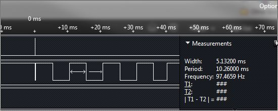
If we hook up the logic analyser we should get a trace which looks something like the following:
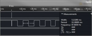
Basic Timer

Basic Timer

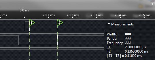
The top trace shows the trigger pulse whilst the trace below shows the output from the timer callback. If we expand the start of the trace we see the following:

Timer with trigger

Timer with trigger

As you can see, there is a small pulse (the trigger) at the start followed by the pulses generated by the timer. The timer between the falling edge of the trigger and the rising edge of the first pulse generated by the timer is approximately 16us. This can be put down to the amount of time it takes for the NETMF instructions to complete the construction of the timer. So the first thing the timer does is to invoke the callback method defined in the constructor.

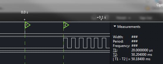
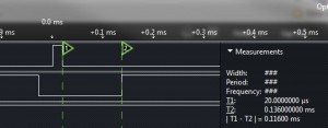
If we modify the construction of the timer slightly we can see the impact of the delay parameter. Let’s change the construction to the following:

oneHundredHertzTimer = new Timer(timerCallback, null, 50, 5);

If we run this application (see the project BasicTimerWithDelay) we will see the following in the logic analyser:

BasicTimer50msDelay

As you can see, the start of the timer has been delayed by 50ms.

Two Timers, One Interrupt

In this example we will look at the role the user defined object has in the TimerCallback parameter. This object can be used to allow the system to use a single callback from multiple timers. The object can be used to determine which timer invoked the callback.

The user defined object is an instance of an object which is passed to the callback method when it is called. In the following we start with an enum:

private enum TimerState { OneHertz, TwoHertz };

Now when we create the timers we create a new object and pass this into the constructor. Our constructors look like the following:

TimerState oneHertzState = TimerState.OneHertz;
oneHertzTimer = new Timer(timerCallback, oneHertzState, 0, 500);
for the one hertz timer and:

TimerState twoHertzState = TimerState.TwoHertz;
twoHertzTimer = new Timer(timerCallback, twoHertzState, 0, 250);

for the two hertz timer.

As you can see, both timers have the same method being invoked as the callback method. However, each timer will pass in a different object (albeit of the same type) to the callback method. We can then use this parameter to determine the action we should take. The code for the callback method will look like the following:

private static void TimerInterrupt(object state)
{
	switch ((TimerState) state)
	{
		case TimerState.OneHertz:
			oneHertzPulse.Write(!oneHertzPulse.Read());
			break;
		case TimerState.TwoHertz:
			twoHertzPulse.Write(!twoHertzPulse.Read());
			break;
	}
}

The full application is as follows:

using System;
using System.Threading;
using Microsoft.SPOT.Hardware;
using SecretLabs.NETMF.Hardware.Netduino;

namespace TimerExample
{
    public class Program
    {
        private static Timer oneHertzTimer = null;
        private static OutputPort oneHertzPulse = null;

        private static Timer twoHertzTimer = null;
        private static OutputPort twoHertzPulse = null;
        
        private static TimerCallback timerCallback = null;

        private enum TimerState { OneHertz, TwoHertz };

        private static OutputPort trigger = null;

        public static void Main()
        {
            trigger = new OutputPort(Pins.GPIO_PIN_D1, false);
            timerCallback = new TimerCallback(TimerInterrupt);
            trigger.Write(true);
            trigger.Write(false);
            //
            //  Set up the one hertz timer.
            //
            oneHertzPulse = new OutputPort(Pins.GPIO_PIN_D7, false);
            TimerState oneHertzState = TimerState.OneHertz;
            oneHertzTimer = new Timer(timerCallback, oneHertzState, 0, 500);
            //
            //  Set up the two hertz timer.
            //
            twoHertzPulse = new OutputPort(Pins.GPIO_PIN_D6, false);
            TimerState twoHertzState = TimerState.TwoHertz;
            twoHertzTimer = new Timer(timerCallback, twoHertzState, 0, 250);
            //
            Thread.Sleep(Timeout.Infinite);
        }

        private static void TimerInterrupt(object state)
        {
            switch ((TimerState) state)
            {
                case TimerState.OneHertz:
                    oneHertzPulse.Write(!oneHertzPulse.Read());
                    break;
                case TimerState.TwoHertz:
                    twoHertzPulse.Write(!twoHertzPulse.Read());
                    break;
            }
        }
    }
}

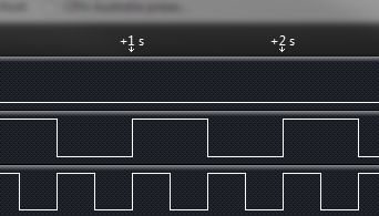
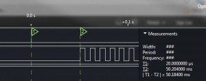
If we run this application we will see the following on the logic analyser:

Two timers with one interrupt.

Two timers with one interrupt.

As you can see, we are generating a one and a two hertz signal using a single callback.

Stopping A Timer

So far we have considered starting a timer and the various options for delaying and callbacks. There will come a point where we will want to stop a timer from executing. A quick glance through the methods provided for the Timer class reveals that there is no method do do this. In this scenario, the first instinct is to simply set the variable referencing to the object to null.

So if we take the first example as out starting point we will add a small amount of code to deal with a button press. The idea is that when the user presses the onboard button on the Netduino Plus 2, the application will terminate the timer by setting to timer object to null. The code becomes:

using System.Threading;
using Microsoft.SPOT.Hardware;
using SecretLabs.NETMF.Hardware.Netduino;
using Microsoft.SPOT;

namespace StoppingATimer
{
    public class Program
    {
        private static Timer oneHundredHertzTimer = null;
        private static OutputPort oneHundredHertzPulse = null;
        private static TimerCallback timerCallback = null;
        private static InterruptPort button = null;

        public static void Main()
        {
            timerCallback = new TimerCallback(TimerInterrupt);
            oneHundredHertzPulse = new OutputPort(Pins.GPIO_PIN_D7, false);
            button = new InterruptPort(Pins.ONBOARD_BTN, true, Port.ResistorMode.PullUp, Port.InterruptMode.InterruptEdgeHigh);
            button.OnInterrupt += new NativeEventHandler(button_OnInterrupt);
            oneHundredHertzTimer = new Timer(timerCallback, null, 0, 5);
            Thread.Sleep(Timeout.Infinite);
        }

        private static void button_OnInterrupt(uint data1, uint data2, System.DateTime time)
        {
            oneHundredHertzTimer = null;
            Debug.Print("Timer set to null.");
        }

        private static void TimerInterrupt(object state)
        {
            oneHundredHertzPulse.Write(!oneHundredHertzPulse.Read());
        }
    }
}

If you deploy this application to the Netduino Plus 2 you will see the same output (on the logic analyser) as the first example in this post. Namely, a 100Hz square wave with a 50% duty cycle.

So the next thing to try is pressing the button and see what happens. If everything works as expected then the timer should be set to null and the timer should terminate. So let’s press the button and start the logic analyser.

And the timer keeps on running. In order to kill the timer we must ensure that it is disposed of correctly. We can do this by modifying the button interrupt method as follows:

private static void button_OnInterrupt(uint data1, uint data2, System.DateTime time)
{
	oneHundredHertzTimer.Dispose();
	oneHundredHertzTimer = null;
	Debug.Print("Timer set to null.");
}

Running the application again and pressing the button results in the expected behaviour.

Changing the Frequency

In our final example we will look at changing the frequency of the timer. This example uses the button press interrupt from the previous example but this time it will halve the period (i.e. double the frequency of the output signal) of the timer. The application uses the Change method to change the timer on the fly. So let’s dive straight in with some code:

using System.Threading;
using Microsoft.SPOT.Hardware;
using SecretLabs.NETMF.Hardware.Netduino;
using Microsoft.SPOT;

namespace ChangingTheFrequency
{
    public class Program
    {
        private static Timer frequencyGenerator = null;
        private static OutputPort frequencyGeneratorOutput = null;
        private static TimerCallback timerCallback = null;
        private static InterruptPort button = null;
        private static int currentPeriod;

        public static void Main()
        {
            timerCallback = new TimerCallback(TimerInterrupt);
            frequencyGeneratorOutput = new OutputPort(Pins.GPIO_PIN_D7, false);
            button = new InterruptPort(Pins.ONBOARD_BTN, true, Port.ResistorMode.PullUp, Port.InterruptMode.InterruptEdgeHigh);
            button.OnInterrupt += new NativeEventHandler(button_OnInterrupt);
            currentPeriod = 500;
            frequencyGenerator = new Timer(timerCallback, null, 0, currentPeriod);
            Thread.Sleep(Timeout.Infinite);
        }

        private static void button_OnInterrupt(uint data1, uint data2, System.DateTime time)
        {
            if (currentPeriod > 100)
            {
                currentPeriod /= 2;
                frequencyGenerator.Change(0, currentPeriod);
            }
        }

        private static void TimerInterrupt(object state)
        {
            frequencyGeneratorOutput.Write(!frequencyGeneratorOutput.Read());
        }
    }
}

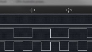
As you can see the code is relatively straight forward. Connecting up the logic analyser and running the application generates a 1 Hz signal (500ms period will result in 1Hz). Pressing the button on the Netduino Plus 2 will cause the period to be halved and hence the frequency to be doubled. You logic analyser will confirm this, I know mine did.

One thing you should note is that the Change method returns a value to indicate if the method has disposed of the old timer. I have never seen this not return true but if you see some odd behaviours with timers still generating interrupts at old frequencies then it may be the result of an old timer still hanging around.

Conclusion

This article was inspired by a posting on the Netduino chatrooms regarding the changing/killing of timers. I must admit I was a little astounded to find that there was no Stop or Start method in the class. As you can see, the techniques for doing this are not complex, they are just not obvious.

There are also some nice feature, like the fact that Timers run in their own threads. Investigation of these features are left as an exercise for the reader.

As always, the Source code is available for download.

STM8S SPI Slave (Part 3) – Making a Go Module

Monday, November 26th, 2012

In this, the last of the series of posts regarding implementing SPI Slave devices using the STM8S, we will look at building a module for the Netduino Go. This post builds upon the two previous posts:

Here we will build upon the buffering and overlay the the Netduino Go 1.0 protocol in order to allow the two devices to communicate. We will also extend the STM8S application to add a simple function table to allow the simple addition of extra functionality to the system.

The makers of the Netduino Go, Secret Labs, have not formally released the GoBus 1.0 specification as a document. They have however release the source code to some of their modules and this can be found in the Wiki. The code found in the Wiki posts along with discussions on various forums has been used in the production of the code presented here. Credit for help is due to Secret Labs for releasing the code and also to the following Netduino forum members:

  • Chris Walker
  • CW2

These forum members have given assistance in one form or another over the past few months and without their help this post would not have been possible.

GoBus 1.0 Protocol

The early GoBus protocol uses an 18 byte data packet which is exchanged by the Netduino Go and the module. This packet of data contains a one byte header, 16 bytes of data and a one byte checksum with the data packets being exchanged over SPI. With the exception of the header and the checksum it appears that meaning of the data within the 16 byte payload is determined by the module developer.

I would also point the reader to the blog post A Developers Introduction to GoBus by Matt Isenhower on the Komodex System web site.

Enumeration

When the Netduino Go is first powered it will look at each of the Go Sockets in turn and attempt to interrogate the modules which are connected to the main board. It does this by sending out a packet with a single byte header 0xfe followed by 16 data bytes and a checksum. From experience, the data bytes are normally set to 0xff.

The module attached to the socket is then required to respond with a header byte of 0x2a followed by the 16 byte GUID of the module and the checksum byte.

The end result of this exchange is that the Netduino Go will have built up a list of modules attached to the main board along with the corresponding socket numbers.

This process then allows the .NET code to connect to a module using the GUID or the GUID and socket number. Successful connection is indicated by the blue LED by the side of the socket being illuminated. A failed connection normally results in an exception being thrown.

Data Transfer/Module Control

When the code running on the Netduino Go has successfully attached to the module on a socket it can start to control/communicate with the module. At this point it appears that the protocol uses the header 0x80 to indicate transfer between the module and the main board. So our data packets remain 18 bytes with the following format:

  • 0x80 – Header
  • 16 byte payload
  • 1 byte CRC

It appears that the meaning of the 16 byte payload is determined by the module developer.

GPIO Interrupt

The protocol also allows for the use of a single GPIO. This can be used as a signalling line to let either side know that an action is pending. Convention appears to be to use this to allow the module to let the code on the main board know that there is some data/action pending.

A Simple Module

We will be creating a simple module to illustrate how the STM8S and the Netduino code work together. In order to use the least hardware possible the module will perform a simple calculation and return the result. Our module will need to perform the following:

  • Enumerate using a GUID allowing the Netduino Go to detect the module
  • Receive a number from the Netduino Go
  • Perform a simple calculation and notify the Netduino Go that the result is ready.
  • Send the result back to the Netduino Go when requested.

This simple module illustrates the key types of communication which may be required of a simple module. It is of course possible to use these to perform other tasks such as controlling a LED or receiving input from a button or keypad.

Netduino Go Module Driver

The Netduino Go code derived from the C# code published by Secret Labs in their Wiki. The major changes which have been made for this post are really concerned with improving clarity (adding comments at each stage to expand on the key points etc.).

Module ID

Modules are identified using a GUID. This ID allows the GoBus to connect to a module by scanning the bus for the specified ID. It also allows the Netduino Go to verify that when connecting to a module on a specific socket that the module is of the correct type. So the first thing we will need to do is obtain a new GUID. There are various ways in which we can do this and the simplest way to do this is to use the Create GUID menu option in Visual Studio. You can find this in the Tools menu.

Once you have your GUID you need to break this down into an array of bytes. You can then enter this in the both the Netduino code and the STM8S code. You will find the appropriate line in the file BasicModule.cs. The code looks something like this:

private Guid _moduleGuid = new Guid(new byte[] { 0x80, 0x39, 0xe8, 0x2b, 0x55, 0x58, 0xeb, 0x48, 0xab, 0x9e, 0x48, 0xd3, 0xfd, 0xae, 0x8c, 0xee });

REMEMBER: It is critical that you generate your own GUID as each module type will need to have distinct ID.

Scanning down the file a little way you will find the two constructors for the class. One takes a socket and attempts to bind to the specified module on the requested socket. The other will attach to the first available module on the GoBus.

Initialise

This method is key to allowing the Netduino Go to connect to the module. The method binds to the module (assuming the IDs match) and retrieves a list of resources which the driver can use to communicate with the module. In this case, the SPI information and the pin used as an interrupt port. The remainder of the method configures the module driver to use these resources.

One key point to note is the use of the AutoResetEvent object. This is used to allow the interrupt handler to communicate the fact that an event has occurred to the methods we will write. This can be done in a manner which is non-blocking.

AddFive Method

This is the first of our methods implementing the functionality which our module will provide. In our case, this method actually implements the simple arithmetic we will be asking the module to perform. We will be sending a byte to the module, the module will add five to the number passed and then make this available to the Netduino Go. The code looks like this:

public byte AddFive(byte value)
{
	int retriesLeft = 10;
	bool responseReceived = false;

	_writeFrameBuffer[0] = GO_BUS10_COMMAND_RESPONSE;
	_writeFrameBuffer[1] = CMD_ADD_FIVE;
	_writeFrameBuffer[2] = value;
	WriteDataToModule();
	while (!responseReceived && (retriesLeft > 0))
	{
		//
		//  We have written the data to the module so wait for a maximum 
		//  of 5 milliseconds to see if the module responds with some 
		//  data for us.
		//
		responseReceived = _irqPortInterruptEvent.WaitOne(5, false);
		if ((responseReceived) && (_readFrameBuffer[1] == GO_BUS10_COMMAND_RESPONSE))
		{
			//
			//  Module has responded so extract the result.  Note we should really
			//  verify the checksum at this point.
			//
			_writeFrameBuffer[0] = GO_BUS10_COMMAND_RESPONSE;
			_writeFrameBuffer[1] = CMD_GET_RESULT;
			WriteDataToModule();
			return(_readFrameBuffer[2]);
		}
		else
		{
			//
			//  No response within the 5ms so lets make another attempt.
			//
			retriesLeft--;
			if (retriesLeft > 0)
			{
				WriteDataToModule();
			}
		}
	}
	throw new Exception("AddFive cannot communicate with the Basic GO! module");
}

The first thing this the method does is to set up the _writeFrameBuffer with the header, the command number and the data we will be sending. The data is then written to the module using SPI.

Next we will wait a while for the module to indicate via the GPIO pin that it has processed the data and the result is ready. As we shall see later, the module has already put the result in the transmission buffer ready for retrieval. This will have been performed before the interrupt was generated. The following line performs the non-blocking check to see if the interrupt has been generated:

responseReceived = _irqPortInterruptEvent.WaitOne(5, false);


responseReceived will be true if the interrupt has been generated and the C# module code has received the event.

The final task is to retrieve the result from the module by sending a retrieve command. This is performed by the following code:

_writeFrameBuffer[0] = GO_BUS10_COMMAND_RESPONSE;
_writeFrameBuffer[1] = CMD_GET_RESULT;
WriteDataToModule();
return(_readFrameBuffer[2]);

STM8S Module

Much of the code required here has already been covered in the previous post, STM8S SPI Slave (Part 2). The protocol uses a small buffer to allow messages to be transferred between the STM8S and the Netduino Go. In order to make this work as a Netduino Go module we need to overlay the GoBus protocol onto the message buffers and provide a mechanism for interpreting these messages. The mechanism we adopted is as follows:

  • All messages will be restricted to 18 bytes (one byte header, 16 bytes payload, one byte CRC)
  • The request header (from the Netduino to the module) will be 0x80 allowing a 16 byte payload
  • The response header (from the module to the Netduino) will be 0x2a followed by 0x80. This restricts the return payload to 15 bytes.
  • The final byte will be a CRC calculated on the header and the payload
    • The way in which the protocol has been implemented here also places a restriction upon on the application. Firstly, the module must receive a request as a full payload. Only then can the module respond. This is where the GPIO interrupt discussed earlier comes into play.

      The final part of the problem is to work out how to dispatch the messages received by the module. To do this we will use a function table.

      For the remainder of this article we will restrict ourselves to looking at the new functionality we will be adding on top of the previous post in order to allow the creation of a module.

      Function Table

      A function table in C is a simple list of function pointers. We will add to this by allowing a variable function identifier to be used to associate a byte ID with a particular method within the module. The following code allows the table to be setup:

      //
      //  Function table structure.
      //
      typedef struct
      {
          unsigned char command;          //  Command number.
          void (*functionPointer)();      //  Pointer to the function to be executed.
      } FunctionTableEntry;
      //
      //  Forward function declarations for the function table.
      //
      void AddFive();
      void GetValue();
      //
      //  Table of pointers to functions which implement the specified commands.
      //
      FunctionTableEntry _functionTable[] = { { 0x01, AddFive }, { 0x02, GetValue } };
      //
      //  Number of functions in the function table.
      //
      const int _numberOfFunctions = sizeof(_functionTable) / sizeof(FunctionTableEntry);
      

      Here we define a function table entry which has a byte ID and a pointer to a function (taking a void parameter list) associated with the ID. We then declare an array of these objects and associate functions with the IDs.

      The final line of code simply determines the number of entries in the function table.

      Using the above table we can work out which function to call using the following code:

      if (_numberOfFunctions > 0)
      {
      	for (int index = 0; index < _numberOfFunctions; index++)
      	{
      		if (_functionTable[index].command == _rxBuffer[1])
      		{
      			(*(_functionTable[index].functionPointer))();
      			break;
      		}
      	}
      }
      

      The function table method presented here allows the functionality of the module to be expanded with relative ease. In order to add a new piece of functionality you simply need to do the following:

      • Create a new method in the STM8S code to implement the new functionality
      • Determine the ID to be used for the functionality and add a new entry to the function table
      • Create a method in the Netduino Go driver to call the method and retrieve any results as necessary

      By performing these three simple steps you can add one or more functions with ease. The communication protocol will continue to work as is with no modification. The only exception to this rule will be cases where more than one payload of data needs to be transferred in order to achieve a specified piece of functionality (say a network driver etc.).

      Buffers and GUIDs

      We will need to make a slight modification to the Rx buffer in order to account for the checksum byte. We will also need to add somewhere to store the GUID which acts as the identifier for this module. This results in the following small change to the global variable code:

      //
      //  Application global variables.
      //
      unsigned char _rxBuffer[GO_BUFFER_SIZE + 1];    // Buffer holding the received data plus a CRC.
      unsigned char _txBuffer[GO_BUFFER_SIZE];        // Buffer holding the data to send.
      unsigned char *_rx;                             // Place to put the next byte received.
      unsigned char *_tx;                             // Next byte to send.
      int _rxCount;                                   // Number of characters received.
      int _txCount;                                   // Number of characters sent.
      volatile int _status;                           // Application status code.
      //
      //  GUID which identifies this module.
      //
      unsigned char _moduleID[] = { 0x80, 0x39, 0xe8, 0x2b, 0x55, 0x58, 0xeb, 0x48,
                                    0xab, 0x9e, 0x48, 0xd3, 0xfd, 0xae, 0x8c, 0xee };
      

      GoBus Interrupt

      The discussion of the code on the Netduino Go driver (on the main board) mentioned the fact that the module can raise an interrupt to signal the fact that an operation has completed and that data is ready for retrieval. In order to do this we raise an interrupt on one of the pins when we have processed the data. This code is trivial:

      //
      //  Raise an interrupt to the GO! main board to indicate that there is some data
      //  ready for collection.  The IRQ on the GO! board is configured as follows:
      //
      //  _irqPort = new InterruptPort((Cpu.Pin) socketGpioPin, false, Port.ResistorMode.PullUp,
      //                               Port.InterruptMode.InterruptEdgeLow);
      //
      void NotifyGOBoard()
      {
          PIN_GOBUS_INTERRUPT = 0;
          __no_operation();
          PIN_GOBUS_INTERRUPT = 1;
      }
      

      This method is simple and really just toggles which is connected to GPIO pin on the Netduino Go socket.

      Adding Functionality to the Module

      In our simple case we need to add two pieces of functionality, the ability to add five to a number and then to allow the caller to retrieve the result. This results in the following two methods:

      //
      //  GO! function 1 - add 5 to byte 2 in the Rx buffer and put the answer into the
      //  Tx buffer.
      //
      void AddFive()
      {
          _txBuffer[1] = _rxBuffer[2] + 5;
          NotifyGOBoard();
      }
      
      //--------------------------------------------------------------------------------
      //
      //  GO! Function 2 - return the Tx buffer back to the GO! board.
      //
      void GetValue()
      {
          NotifyGOBoard();
      }
      

      SPI Go Frame

      The implementation of the SPI processing here is interrupt driven. As such we will need to allow a method of synchronising the payloads we receive. This application will do this using the rising edge of the chip select signal which is generated by the Netduino Go main board. This allows us for cater for the many scenarios (synchronisation, underflow and overflow).

      In the case of underflow and synchronisation, the chip select signal will rise before we have enough data. In this case we have either a corrupt packet or we have started to recei8ve data part way through the packet. In this case we cannot sensibly process the data so we should throw away the packet and wait for the next one.

      An overflow situation can occur when the Netduino Go sends more than 18 bytes in one packet of data. In this case we should detect this and prevent the buffers from overflowing.

      In order to allow for these cases we reset the Go frame pointers when the chip select signal changes from low to high:

      //
      //  This method resets SPI ready for the next transmission/reception of data
      //  on the GO! bus.
      //
      //  Do not call this method whilst SPI is enabled as it will have no effect.
      //
      void ResetGoFrame()
      {
          if (!SPI_CR1_SPE)
          {
              (void) SPI_DR;                          //  Reset any error conditions.
              (void) SPI_SR;
              SPI_DR = GO_FRAME_PREFIX;               //  First byte of the response.
              _txBuffer[0] = _moduleID[0];            //  Second byte in the response.
              //
              //  Now reset the buffer pointers and counters ready for data transfer.
              //
              _rx = _rxBuffer;
              _tx = _txBuffer;
              _rxCount = 0;
              _txCount = 0;
              //
              //  Note the documentation states this should be SPI_CR2_CRCEN
              //  but the header files have SPI_CR_CECEN defined.
              //
              SPI_CR2_CECEN = 0;                      //  Reset the CRC calculation.
              SPI_CR2_CRCNEXT = 0;
              SPI_CR2_CECEN = 1;
              SPI_SR_CRCERR = 0;
          }
      }
      

      As we shall see later, the end of the SPI transmission with result in one of the following cases:

      • Too little data received correctly. The rising chip select line will reset the buffer pointers and the data will be discarded.
      • The correct amount of data received. In this case the buffer will be processed correctly.
      • Too much data is received. The excess data will be discarded to prevent a buffer overflow.

      The ResetGoFrame method is key in ensuring that the buffers are reset at the end of the SPI transmission indicated by the rising chip select line.

      SPI Tx/Rx Interrupt Handler

      This method is responsible for ensuring that the data is transmitted and received correctly. It works in much the same way as the previous buffered SPI example. The main difference between this module and the previous example is what happens when the first byte of the data received is equal to 0xfe. In this case the Tx buffer pointer is moved to point to the module ID. This ensures that the Netduino Go receives the correct response to the enumeration request.

      Connecting the Boards

      The application code contains a number of #if statements to take into account the differing pin layouts of the microcontrollers used. The following have been tested so far:

      • STM8S103F3 TSSOP20 on a breadboard
      • STM8S Discovery

      The Protomodule has also been wired up for one particular module but at the time of writing the definitions have not been added to the sources.

      In order to connect the Netduino Go main board to a module in development you will probably need to purchase some form of breakout such as the Komodex breakout board (Straight connectors or 90-Degree connectors).

      Connecting the two boards should be a simple case of ensuring that the SPI pins are connected MOSI to MOSI, MISO to MISO, CS to CS and Clock to Clock. In the case of the Discovery board I used PB0 for the CS line and for the STM8S103 setup I used the standard pin PA3.

      Running the Code

      Running the code should be a simple case of loading the STM8S code into the IAR development environment first and the deploying the code to the chip. Hot F5 to run the code.

      Next, load the visual studio code and deploy this to the Netduino Go main board. Hit F5 to run the code.

      The C# code running in Visual Studio should start to print some diagnostic information to the debug window. You should see a series of statements of the form Adding 5 to 6 to give 11. The 6 is the parameter which has been sent to the module for processing and the 11 is the result.

      Observations

      I have seen differing behaviours to the way in which the debugger in IAR works with the code in the module. Occasionally the debugger will actually prevent the module from enumerating. This will result in an exception in Visual Studio. To date I have only seen this behaviour with the STM8S103 setup. The STM8S Discovery board seems to work correctly. If you have problems with this then the only suggestion is to detach IAR from the board and rely upon diagnostic information being dumped to a logic analyser. You will note that the test application which runs on the Netduino Go has the instantiation of the module wrapped in a while loop and a try block. This allows the test code to make several attempts at creating a new module instance. This should not be necessary in the final production code as this has not yet failed in a none debug environment.

      This code has been tested with the simple module example here and also with a temperature and humidity sensor. The application enumerated OK and has been soak tested in two environments over a period of hours. The code seems to be stable and works well with the Netduino Go.

      I originally tried to be ambitious with the interrupt service routine dealing with the chip select line. This gave me code which was simpler but lead to a timing issue. As it stands at the moment, dropping the chip select line from high to low starts the SPI processing. The time between this happening and the first clock transition is only 3.25us as measured on my logic analyser. This means that all of the preparation must be completed in 3.25us.

      If we look at the diagram below you can see the timings at the start of the SPI communication:

      SPI Timing Diagram

      SPI Timing Diagram

      The two markers 1 & 2 indicate the time we have between the start of the comms indicated by CS falling to the first clock pulse. The Status Code trace is a debugging signal generated by the application. The rising edge indicates when the first line of the interrupt service routine for the CS line starts and the falling edge indicates the point where we have completed enough processing to allow SPI to be enabled.

      Conclusion

      This post shows how we to create a Netduino Go module using a standard communication protocol. Additional module functionality can simply be added by adding to the function table.

      As noted at the start, this article is the combination of information provided by Netduino community members along with the module code which can be found in the Wiki.

      As usual, the source code for this application is available for download (STM8S Go Module and Netduino Go – Basic Module Driver).

      Source Code Compatibility

      SystemCompatible?
      STM8S103F3 (Breadboard)
      Variable Lab Protomodule
      STM8S Discovery

Komodex Seven Segment Display and Breakout Modules

Friday, July 27th, 2012

Komodex Labs recently released a couple of new modules for the Netduino GO! platform. The first is a seven segment display module and as we will see later this can be used to show sensor data. The second module is a breakout module for the GO! bus and this is probably more interesting to module developers.

As the postman was kind to me and managed to get these modules to me this week I thought I’d hook them up to the light sensor I have been playing with to see what they can do.

A Little Background

I have recently been working with a simple sensor to teach myself how to work with the STM8S. It has been a long slow task as the normal competing pressures of work, the house and general life stuff keeps calling for my attention.

The project uses a TSL235R sensor which converts the current ambient light level into a square wave with 50% duty cycle. The STM8S periodically reads the frequency of the signal generated by the sensor. This value is then made available to the Netduino GO! via the GO! Bus.

This project is going to read the value from the STM8S and display it on the seven segment display. The value is a 16-bit value and so can range from 0 to 65535 so we will be showing the value in hex.

Seven Segment Module

The seven segment display is a nice little module very professionally finished. It feels a solid – sort of odd to say that about a module. I was kind of surprised by the weight but then I have only been working with small modules so far.

I’d write more but I think the module is best described my Matt’s blog post. This shows some photos of the module along with a description of the API used to control it.

GO! Bus Breakout Module

This is a handy little module which only had a short production run. I was lucky enough to have ordered one before stock ran out. The module is aimed at module developers. It has a couple of sockets for module cables along with some handy breakout points.

Komodex Labs GO! Bus Breakout Module

Komodex Labs GO! Bus Breakout Module

The idea is simple, you connect your Netduino GO! to one side of the breakout board and your module to the other side of the breakout board. You can then hook up test equipment (scope / logic analyser etc.) to a row of headers on the board. This allows you to debug your module by snooping on the data going down the GO! Bus.

An alternative configuration and one I am using for development on breadboard, is to connect the breakout module to breadboard with the Netduino GO! connected to one side of the breakout board. This allows you to feed the GO! Bus signals into your circuit whilst at the prototype stage.

The breakout also has a lovely feature in that you can connect the ST-LInk/V2 module to the board and at the flick of a switch you can disconnect the SWIM/NRST signals from the Netduino GO! and connect them to the ST-Link/V2 instead. This allows you to re-program the STM8S on the fly without having to modify your circuit – NEAT !

For more information about this module I’d head over to Matt’s blog post.

Hooking it all up

Connecting the Seven Digit Module up to the go was easy, it simply needed a standard 5cm GO! Bus cable and that’s it.

The Breakout module was a little more difficult as it had to be hooked into an existing prototype circuit. From the Netduino side it was easy, just another 5cm GO! Bus cable. The ST-Link/V2 connection was also easy as the module has a connector already on the board and it is designed to ensure that the connection can only be made one way. The only complication was then ensuring that the connections between the GO! Bus and the prototype circuit were correct. Adding this module has in fact made my prototype circuit a little cleaner.

Here’s what the final circuit looks like:

Komodex Seven Segment in Light Sensor Prototype Circuit

Komodex Seven Segment in Light Sensor Prototype Circuit

Installing the Drivers

The Seven Segment Module is supplied with a set of drivers in the form of an executable. The drivers can be found on the Komodex Labs web site. Installation was quick, simple and painless.

Komodex Labs also provide the source code for the drivers along with a sample application. This is a separate download and as you will see later, this came in handy.

As you would expect, the breakout module does not require any drivers as there is no interaction between the module and the PC.

Writing the Software

The API provided with the module is comprehensive but in this case we are going to use only a small part of it. We need to display a hex representation of a 16-bit number.

So the first step is to create a new project and add a reference to the module. You will have to browse to the directory in which you installed the drivers and add the Komodex.NETMF.SevenSegmentDisplay.dll file. On my machine this was installed in C:Program Files (x86)KomodexModule DriversAssembliesv4.2

The next step is to add a using statement

using Komodex.NETMF;

and then declare and instantiate an instance of the module:

SevenSegmentDisplay display = new SevenSegmentDisplay();
display.SetValue(0);

The above shows the module being instantiated and the display value set to 0.

The remainder of the program continuously polls the sensor for a reading. This reading is converted into a string containing the hexadecimal representation of the reading. This reading is then displayed on the Seven Segment Module. The code looks something like this:

while (true)
{
	short diff = module.GetReading();
	string output = "";
	char c;
	for (int index = 3; index >= 0; index--)
	{
		int nibble = (diff >> (4 * index)) & 0xF;
		if (nibble < 10)
		{
			output += nibble.ToString();
		}
		else
		{
			c = (char) ('A' + nibble - 10);
			output += c.ToString();
		}
	}
	display.SetValue(output);
	Thread.Sleep(1000);
}

The line short diff = module.GetReading(); obtains a reading from the sensor module which I am prototyping. This value could come from any sensor or from any source / calculation.

Hitting F5 deployed the code to the Netduino GO! and values quickly started appearing on the display. Success!

No… Wait…

I’m getting some unexpected output. Every now and then the module displays a number with some spaces in place of digits. Hmmmmm… what is going on!

Time for a quick test program. I know that the module works OK as the test projects ran fine. Adding a Debug.Print of the output variable gave me a clue. There was a pattern. Any numbers with the digit 9 in them showed a space instead of a digit. A quick test program showed that displaying 2929 where the variable of type int displayed the number correctly. Doing the same where the value was stored in a string showed any digit except the digit 9, these were replaced with spaces. Now we know where the problem is.

As noted earlier, Komodex Labs supply the source code for the drivers. So opening this project and some poking around the code for the display resulted in the problem being found. A quick modification to the source, recompile and then reference the newly compiled DLL in my code and Success !

Edit: Komodex labs have confirmed that the driver has been patched and as of 27/07/2012 the driver download contains the fix for the problem noted.

Here is a short video of the sensor and display working together:

The Cube Still Lives…

Monday, May 21st, 2012

The 8 x 8 x 8 LED cube has been on it’s travels again. This time it has made an appearance at the Bay Area Maker Faire:

Netduino 8x8x8 LED Cube at the Bay Area Maker Faire 2012

Thanks to fellow Netduino community member Chris Hammond for permission to use this photo.

Netduino Starter Kit

Saturday, April 21st, 2012

My Netduino Starter Kit finally arrived from the USA this morning. The days plans are a long and distant memory as boy must play with toys! So here is a short video I made of my first project.

Netduino Go

Thursday, April 5th, 2012

The Secret Labs team have just release a new product, Netduino Go. This is a NET MF board based on the STM32F4 family of chips. For more information have a look at:

Netduino Home Page
Launch Announcement in Community Forums

Software for the LED Cube

Sunday, March 18th, 2012

So you’ve built is and now we need some software to run it. To do this we are going to need to perform two tasks at the same time:

  • Calculate what we are going to display in the cube
  • Run the display

Multithreading is used in order to achieve this. The program has one thread which does nothing but cycle through each layer one by one shifting the data for the layer into the shift registers and then turning the layer on.

The second thread prepares the next item to be displayed and then passes this on to the cube to display.

LEDCube Class

This is a relatively simple class having a single constructor and two methods. The constructor sets the scene for us and makes sure everything is ready to use:

public LEDCube()
{
    config = new SPI.Configuration(SPI_mod: SPI.SPI_module.SPI1,
                                   ChipSelect_Port: Pins.GPIO_PIN_20,
                                   ChipSelect_ActiveState: false,
                                   ChipSelect_SetupTime: 0,
                                   ChipSelect_HoldTime: 0,
                                   Clock_IdleState: true,
                                   Clock_Edge: true,
                                   Clock_RateKHz: 100);

    spi = new SPI(config);
    buffer = new byte[64];
    for (int index = 0; index < buffer.Length; index++)
    {
        buffer[index] = 0;
    }
}

The buffer contains the data we are going to be showing in the cube.

The next two methods perform the work or updating and displaying the buffer. We need to be careful that the buffer is not updated whilst we are trying to update the display.

public void UpdateBuffer(byte[] newValues)
{
    lock (buffer)
    {
        for (int index = 0; index < buffer.Length; index++)
        {
            buffer[index] = newValues[index];
        }
    }
}

The lock statement helps us to achieve this by locking the buffer so we can copy data into it and also stop the display method from trying to read the buffer and show the data.

The display method is a little longer:

public void DisplayBuffer()
{
    while (true)
    {
        lock (buffer)
        {
            byte[] displayData = new byte[8];

            for (int row = 0; row < 8; row++)
            {
                int offset = row * 8;
                for (int index = 0; index < 8; index++)
                {
                    displayData[index] = buffer[offset + index];
                }
                enable.Write(true);
                bit0.Write((row & 1) != 0);
                bit1.Write((row & 2) != 0);
                bit2.Write((row & 4) != 0);
                spi.Write(displayData);
                enable.Write(false);
            }
        }
    }
}

This method again uses the lock statement to lock the buffer. This means we cannot update the buffer until a full cube of data has been displayed. The method takes a block of 8 bytes representing a layer and then writes this to the shift registers using SPI. Note that the spi.Write is embedded in the writes to the enable line. This ensures that all of the layers are turned off whilst we are updating the shift registers.

Wrapping all of this in the LEDCube class means that we now have a very simple class where we can spawn the DislpayBuffer method into it’s own thread. So off to out Main program. We are going to need an instance of the cube and a buffer to hold the next “frame” we wish to display.

private static LEDCube cube = new LEDCube();
private static byte[] nv = new byte[64];

The first thing we do when entering the main program is to set all of the values in the buffer (set them to zero) and to start the display thread going:

ClearCube();
Thread display = new Thread(new ThreadStart(cube.DisplayBuffer));
display.Start();

ClearCube does just that, sets the values to zero and then calls the cube Update method to copy this zeroed buffer into the cube buffer.

The next line spawns a new thread which runs the DisplayBuffer method and the following line starts it.

At this point we have two threads, the main program loop and the display thread. We can now perform calculations in the main program loop and call cube.UpdateBuffer when we have new data to display.

So how about something to display, a little rain perhaps:

private static void AddDrops(int count, int plane = -1)
{
    for (int drops = 0; drops < count; drops++)
    {
        bool findingSpace = true;
        while (findingSpace)
        {
            int x = rand.Next() % 8;
            int y = rand.Next() % 8;
            int z;

            if (plane == -1)
            {
                z = rand.Next() % 8;
            }
            else
            {
                z = plane;
            }

            int position = ( z * 8 ) + y;
            byte value = (byte) ((1 << x) & 0xff);
            if ((nv[position] & value) == 0)
            {
                nv[position] |= value;
                findingSpace = false;
            }
        }
    }
}

private static void Rain(int noDrops, int cycles)
{
    ClearCube();
    AddDrops(noDrops);
    cube.UpdateBuffer(nv);
    for (int currentCycle = 0; currentCycle < cycles; currentCycle++)
    {
        int bitCount = 0;
        for (int plane = 0; plane < 8; plane++)
        {
            byte value = 1;
            for (int bit = 0; bit < 8; bit++)
            {
                if ((nv[56 + plane] & value) > 0)
                {
                    bitCount++;
                }
                value <<= 1;
            }
        }
        for (int plane = 7; plane > 0; plane--)
        {
            for (int currentByte = 0; currentByte < 8; currentByte++)
            {
                nv[(plane * 8) + currentByte] = nv[( (plane - 1) * 8 ) + currentByte];
            }
        }
        for (int b = 0; b < 8; b++)
        {
            nv[b] = 0;
        }
        AddDrops(bitCount, 0);
        cube.UpdateBuffer(nv);
        Thread.Sleep(75);
    }
}

AddDrops simply adds a specified number of rain drops to the buffer. It also makes sure that if asked for 10 it will always add 10 by checking to see if one exists in the location it wanted to use.

Rain adds the specified number of drops to the buffer, shows the drops and then moved them all down by one plane. Before doing this it counts how many drops are going to fall out of the cube. After all the drops have moved down one plane it adds the drops which have disappeared out of the bottom of the cube back in at the top in random positions.

We can display this by adding this to the main program:

while (true)
{
	Rain(10, 60000);
}

The full source code to this project is current hosted on Codeplex.

Conclusion

Hope that you enjoy trying out this project but be aware that it takes time. This consumed a lot of my spare time for about three weeks. There are still some tasks to complete

  • Power supply
  • A case
But the main stuff is working.

I have not covered the power regulation but you should make sure that you have a regulated 5V DC power supply capable of about 2A – but more would be better. I did actually add my own regulator to this project but it got very hot when the cube was fully lit. Beware – make sure you have a stable supply capable of supplying enough juice.

The Controller Board

Sunday, March 18th, 2012

Having a cube of LEDs is of little use without a controller board. As previously mentioned, all 512 LEDs can be controlled from just 7 lines from the Netduino Mini. As you will have seen during the testing, we can turn on any LED by connecting the anode to a positive supply and the entire layer in which it sits to ground.

The positive supply is a relatively simple thing to achieve and our good friend the 74HC595 shift register will help us there. Connecting to ground requires a little more work but this is achieved using the 74HC238 and a bank of transistors. At the end of this process I had the following board:

Annotated Controller Board

So, a quick walk around the board. Box one contains the Netduino Mini. The two connectors to the bottom left of the board allow the Mini to be connected to the computer – they are the Mini’s COM1 connections. The two connectors at the top right are for the ground and the 5V from my USB – FTDI connector. Only ground is connected, the other connector allows me to stop the 5V lead from flying around and touching something it shouldn’t.

Box 2 contains the bank of 8 x 74HC595s, current limiting resistors and a connector to allow a ribbon cable to be connected the cube to the controller. These will determine which of the LEDs received power. Each of the shift registers will control one row of LEDs, 8 rows need 8 registers. So the shift registers can control 64 LEDs at once.

The remainder of the electronics on the board determine which layer will be connected to ground. The 74HC238 takes four lines from the Mini. Three of the lines represent a binary number 0-7, the fourth line is an output enable line. The decoder takes the number and switches on one of one of the output lines. This is in turn connected to the base of a TIP122 transistor. Applying power to the base allows the layer the transistor is connected to connect to ground.

So all is in place to use persistence of vision to be used to give the appearance that the cube is permanently switched on. Starting with the cube switched off we load the shift registers with the data for layer 0. We then load the 74HC238 with 0 and enable the output. This will turn on the transistor for layer 0 which will allow current to flow through the LEDs in layer 0. We then turn the cube off by disabling the output of the 74HC238 and repeat for layer 1 and so on.

Shift Registers

A little more repetition – don’t you just love it. The eight shift registers are wired together in a cascade with the shifted output of one register forming the input of the next. By connecting eight together we can control 64 outputs.

The basic connections for the shift registers is as follows:

Schematic for the Cascaded Shift Registers

This needs to be repeated until all eight of the registers are connected as in the above diagram. In the controller board diagram the serial data in wires are blue, the clock wires are white and the enable wires are yellow.

Note that a 100nF ceramic capacitor is connected between power and ground and one is placed by each IC as close to the IC as possible.

The current limiting resistors for this project were selected to keep the current per LED at 25mA per LED. The nearest value actually puts this at 26mA per LED. Multiplying this up means that a layer when all of the LEDs are switched on will draw 1.6A. The maximum output current rating per pin on the 74HC494 is 35mA so we are getting close to the limit per pin.

Layer Switching

Layer switching is achieved by connecting a layer to ground through a TIP122 transistor. This should be capable of sinking 2A which is greater than the 1.6A which we could theoretically need to sink if all of the LEDs on a layer are switched on. The 74HC238 selects which layer is connected to ground – or in fact none of them may be connected if the output from the 74HC238 is disabled. The circuit diagram for this part of the controller looks as follows:

Layer Selection Schematic

Again, a 100nF capacitor is placed across power and ground for this IC.

Connecting the Controller to the Cube

The collector for each of the TIP122’s should be connected to a different layer. I connected mine with layer zero being the top layer.

Each of the shift registers should be connected to one row of LEDs. I connected mine with bit zero at the right of the cube. This was done with one of the female connectors (to fit the male connector on the controller board) and some ribbon cable.

The result of these two wiring decisions was a rather odd co-ordinate system. You may decide to use something more conventional.

Adding the Netduino Mini

The Netduino Mini connections have already been noted on the above schematics.

Making the Cube

Sunday, March 18th, 2012

For the majority of June I was working on making the LED cube featured in my previous post. The next few posts will cover making the cube and writing the software which controls it.

The initial post of the cube working first appeared on the Netduino forums in early July. As you can see, it received some good responses.

This project will require the following materials:

Description Quantity
LEDs (use which ever colour floats your boat – I went for blue) 512
74HC595 Shift Registers 8
74HC238 3 to 8 line decoder 1
Netduino Mini 1
16 Pin DIL Socket 9
24 Pin DIL Socket (0.6″) 1
TIP122 NPN Transistor 8
100nF Ceramic Capacitor 10
2.2K Resistor 8
68 Ohm 0.25W Resistor (you may need to change these depending upon the LED you choose) 64
8 Way Single Row Socket 8
36 Way Header Strip (Straight) 2
2 Way Single Row Socket 2
2 Way PCB Mount Terminal Connector 1
8 Way Ribbon Cable 2.5 metres
Wire and connectors Miscellaneous
Pad board 160 x 115 Hole 1
Hex PCB spaces, M3 threaded and M3 screw 4

As well as the above you will need the following items:

  • 5V Power capable of delivering 2A;
  • Solder – I used about 15 metres over the life of this project;
  • Wood to make a template.

As well as the physical items you will need a fair amount of patience and good attention to detail. There are a lot of repetitive tasks in this project. The method is detailed in the three articles listed at the head of this article.