Making a Cube of LEDs
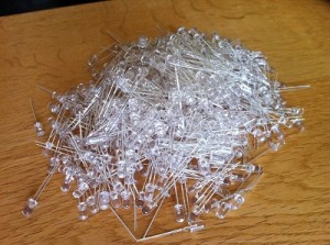
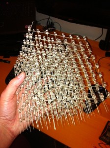
This is probably the most time consuming part of the project requiring a lot of patience, testing and a 30cm x 30cm piece of wood. Seriously, you’ll need a piece of wood. Here we are going to convert this:
Into this:
Working out the Dimensions of the Cube
The exact dimensions of the cube will depend upon the length of the legs on the LEDs. The legs will be soldered together with the cathodes of the LEDs forming a horizontal plane and the anodes connecting the layers vertically.
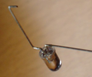
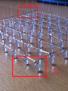
Take one of the LEDs and bend the cathode at a point as close to the body of the LED as possible. The cathode should be at 90 degrees to the anode and parallel to the flat base of the LED. Now bend the top 3mm of the leg of the anode through 90 degrees. You are aiming for something which looks like this:
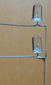
In the final cube we want all of our LEDs to be above each other. If we don’t then each layer will be slightly offset from the on beneath it. We won’t have a cube more of a leaning tower. So the final act of manipulation for the LED is to bend the anode of the LED slightly out from the body of the LED and then to straighten the anode again. The effect should be that the 3mm at the end of the anode should be enough to place the LEDS above each other. When they are connected in the cube they should look like this:
Layer Template
Measure the distance from the centre of the now horizontal cathode to the end of the leg and subtract about 2mm. This will tell you how far apart the LEDs are in the horizontal plane. The 2mm will be used to overlap with the neighbouring LED and will be used to connect the cathodes. Now this is where the wood comes in. You need to drill a grid of holes 8 x 8 which are each this measured distance apart. You will end up with a template in which you can place the LEDs in each layer making soldering easier.
The holes in the template must be small enough to hold the LED firmly but not too firm. The LEDs will need to be removed later without placing too much strain on the soldered joints.
Building the Layers
So now let’s get the soldering iron warmed up and on with the first layer. Take 8 of the LEDs and place them along the top row with the cathodes all pointing to the right (or left if you prefer). The cathodes of the 7 LEDs to the left will overlap slightly with the LED to the right. The rightmost cathode will go off into space. Solder the cathodes together. Congratulations, you now have a line of LEDs.
Now let’s add the remaining LEDs in the layer. I started on the left as I hold the soldering iron in my right hand. Take another 7 LEDs and place these under the top row down the far left column. Again the cathodes should be overlapping. Solder these together. Repeat with the remaining columns. At this point you should have a horizontal row of LEDs connected together with 8 strings of 7 LEDs hanging from it. Eventually you should have something looking like this:
Now test the layer. Simple enough, you just need a power supply and a current limiting resistor. For the LEDs I had chosen a 5V supply fed through a 68 Ohm resistor is adequate. Connect ground to the cathode of the LED which is flying off into space (remember, it’s on the top row, to the right). Now touch each leg of the LEDs in turn with the positive output of the supply (through the current limiting resistor of course). The LEDs should light up and as you touch the anode.
One final bit of soldering is to add a stiffening wire to the layer. Cut and strip a piece of wire. The wire should be long enough to cross the entire layer. Now solder the stiffening wire to the cathodes along the bottom of the layer. See the image above. One thing to note here is that although one piece of wire is sufficient, adding one or two more would not harm.
At this point you will have one complete layer. Time to remove it from the template. This should be done carefully so that you do not put too much stress on the joints. Lifting it up gently with a screwdriver should help. Do not be in a hurry, gently freeing the LEDs first may help. Put this layer to one side and repeat another 7 times.
Connecting the Layers
Now that we have all of the layers built I suggest that they are tested once again. This repeated test may save you pain later. Just imagine how difficult it will be to fix a bad joint in the middle of the cube. We are just checking that the LEDs are still connected and none of the joints have been broken removing the layers from the template.
Now drop one of the layers back into the template. What we now need to do is to place a second layer on top of this one so that the anodes of the layer in the template touch the anodes of the LEDs in this layer. Once in place we need to solder the anodes together – good game, good game. I had the advantage of having a few clamps which could be adjusted vertically as well as horizontally. I would imagine that cardboard (or wood) shaped to the correct height should help support the layers. Remember that whatever you use you will need to be able to remove it without damaging the cube.
Now you have the layer supported, solder the anode of the LEDs in the top layer to the anode of the LED in the layer directly beneath it. Once this has been done – test. Connect the cathode of the bottom layer to ground and touch each of the legs on the top layer in turn with the +ve supply (going through the current limiting resistor). The LED on the bottom layer should light. Move the cathode to the top layer and repeat the test, this time the LED on the top layer should light.
Repeat adding the remaining layers. Just for safety, I would test every layer in the cube as it is built up. This repeated testing sounds like a big overhead but trust me it’s worth it.
So at this point you should now have a cube and if you are like me, lost two days of your life in pursuit of happiness and all that is good in life.
Tags: Electronics, LED, Netduino
Sunday, March 18th, 2012 at 5:00 pm • Electronics, Netduino • RSS 2.0 feed Both comments and pings are currently closed.