RSS

Archive for the ‘Netduino’ Category

NE555 Calculator and Data Logger

Saturday, March 5th, 2011

A while ago I wrote about my renewed relationship with the NE555 when I produced a simple astable circuit. The experience of trying to work out the values lead me to think about writing a calculator application. This lead me to wonder how I could validate the results given that I do not have an oscilloscope – simple add a data logger to the Netduino and use that. The following shows how I did it and provides some information about how the code works.

Objective

Write application which provides the functionality:

  1. Given a set of components and/or the frequency of the circuit calculate the missing value for the components or frequency
  2. Present the results to the user
  3. Capture data on the Netduino on one of the analog pins
  4. Transfer the data from the Netduino and plot the results

This will require two applications, one to interact with the user and perform the calculations and data plotting and one application to capture the data on the Netduino.

Netduino Application

This application is an extension to the Silverlight application which I documented here. This has the core functionality required to allow the Netduino Plus to communicate with a Silverlight application. A few slight changes were required, namely:

  1. Make the web server understand the commands which would be issued by the Silverlight application
  2. Implement a data logger.

For the first of the changes we simply need to add some additional variables to store the configuration and modify the ProcessCommand method. The system uses the Command.html special file (as before) to receive commands/requests from the user. The valid actions implemented are as follows:

ActionParametersDescription
tTest the connection. This simply returns a Hello string to the calling application.
gGet the preconfigured file and send this back to the caller.
cSampleRate and FileNameConfigure the Netduino data logger. The system will configure the Netduino to log data every SampleRate milliseconds and store the results in the specified file.

The last part of the change to the web server is to provide a mechanism to communicate the change to the data logging component. This done using an event as the data logger and the web server are executing in different threads.

The next change required is to implement the data logging functionality. The data logging runs in the main thread. The on board switch was used to trigger data collection rather than having the Netduino log data permanently. The on board LED was also used to indicate if the board is collecting data. A Timer was used to trigger the collection of data from the analog pin. This meant that the board can capture at most 1000 samples per second.

private static void onBoardButton_OnInterrupt(uint data1, uint data2, DateTime time)
{
    if (data2 == 0)
    {
        if (_logging)
        {
            _timer = null;
            _onBoardLED.Write(false);
            _logging = false;
        }
        else
        {
            using (TextWriter tw = new StreamWriter(@"SD" + _fileName, false))
            {
                tw.WriteLine("Ticks,Data");
                tw.Close();
            }
            _startTime = Utility.GetMachineTime().Ticks;
            _timer = new Timer(new TimerCallback(CollectData), null, 0, _sampleRate);
            _onBoardLED.Write(true);
            _logging = true;
        }
    }
}

This code is tied to the on board switches interrupt. It starts and stops the logging depending upon the current state. A logging start request opens the specified file and puts the header into the file. This effectively deletes and results already stored in the file. The timer is created and tied to the CollectData callback. This callback simply reads the pin and writes the number of ticks since the start of the logging session along with the reading from the pin.

private static void CollectData(object o)
{
    string data;

    data = Utility.GetMachineTime().Ticks - _startTime + "," + _analogInput.Read();
    using (TextWriter tw = new StreamWriter(@"SD" + _fileName, true))
    {
        tw.WriteLine(data);
        tw.Close();
    }
}

Silverlight Application

This is where the project began to take on a life of it’s own. The code discussed here consumed the majority of the time spent on the project. The code is fairly well commented and so the main features will be discussed here.

The project uses MVVM to implement a calculator for the NE555. This results in little code in the code behind for the main page. What code there is simply creates a new instance of the View Model class and calls methods in the class when buttons on the interface are clicked. The remaining communication is achieved using data binding in Silverlight.

The calculator can be used to calculate one of the following (given the remaining three values):

  • R1
  • R2
  • C1
  • F

The system takes three of the specified values and calculates the remaining. The values for the components can come from three sources, a standard component, a user specified value or a range of values.

If single component values are used (either standard components or user values) then a single result set is generated. If a range of values are selected for one or more of the components then the system will generate a table of values with one line for each of the requested values.

So much for discussing the application, it is probably just as easy to try the application which can be found here.

The first tab (Parameters on the application collects the parameters for the calculations and allows the user to request that the results are calculated.
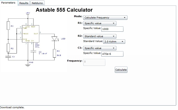
NE555 Calculator

NE555 Calculator

The next tab (Results) presents the results of the calculation.

The final tab (Netduino) allows the application to communicate with a Netduino Plus.

NE555DataLogger

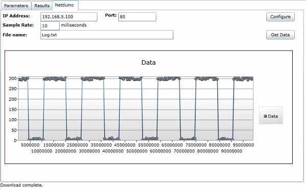
Although the Silverlight application is hosted on my web site, you can still use this to communicate with your Netduino Plus if it is connected to your network.

Results

The resulting application is more or less complete. There are a few things which could be done to make it more robust or more useful, namely:

  1. Add data validation to the properties in the NE555Calculator class.
  2. Make the data logger work with multiple files.
  3. Allow the configuration of the pin used to collect data.
  4. Use the date and time to record when the sample was taken
  5. Collect multiple samples at the same time
  6. Allow the user to enter the reference voltage and scale the data items plotted accordingly
  7. Convert the ticks into milliseconds

These are left as an exercise for the reader.

Source Files

The source files for this project can be found here:

SimpleWebServer.zip

Astable NE555 Silverlight Calculator

As usual, these sources are provided as is and without warranty. They are used at your own risk.

Setting This Up

The Silverlight application can be run from a web site or from Visual Studio. The web server needs a little more than just running the project on the Netduino. You will also have to place the clientaccess.xml policy file on the SD card as Silverlight requests this file in order to determine if it allowed to talk to the web server.

Analog Input

Saturday, February 12th, 2011

The aim of this experiment was to test the analog input.  The simplest way I could think of to do this is to hook up a potentiometer to one of the analog pins and then display the values using the debugger.

First task is to wire up the board.  The final wiring looked like this:

I say final wiring as my initial version looked a little different.  The first version did not have the 3.3V output connected to Aref and as a result I found myself getting very odd results from the analog input pin.

The code to read data from the Netduino looks like the following:

public static void Main()
{
    AnalogInput analog;

    analog = new AnalogInput(Pins.GPIO_PIN_A1);
    analog.SetRange(0, 1023);
    while (true)
    {
        Debug.Print(analog.Read().ToString());
        Thread.Sleep(1000);
    }
}

Running the application and turning the potentiometer results in a range of values from 0 to 1023.

RGB LED and PWM

Saturday, February 12th, 2011

Lots of abbreviations in this post but the aim is simple. Going back to working with LEDs, the idea is to control a RGB LED using the Netduino. The LED I have purchased is a common cathode LED the details of which can be found here.

The LED can be used either as a status display (using each of the three colours for a different status) or the three colours can be mixed to provide mixed colour output. This entry describes how to use the Netduino to provide a mixed colour output using PWM.

Wiring Up The Circuit

The LED is a common cathode LED with three anodes, one for each colour (Red, Green and Blue). This will require three pins on the Netduino in order to control the changing colours. Each of the three pins will require a current limiting resistor in order to ensure that we don’t try to draw too much current from the Netduino and burn out the pins. A quick application of Ohms law to ensure that we do not try and draw more than 8mA gave the following nearest equivalent resistors:

ColourVoltageResistor
Red2V220 ohms
Green3.2V20 ohms (2 x 10 ohms)
Blue3.2V20 ohms (2 x 10 ohms)

The next step is to hook up the LED to the Netduino. This is done using three of the four PWM pins on the board. By using PWM we can vary the power supplied to each of the three pins on the LED. This will allow control of the amount of each colour generated which in turn will determine the colour of the LED. The image below shows the circuit set up on breadboard:

Software

The software uses PWM to control the power supplied to the LED. I found two articles which helped in understanding how this works, the first on Wikipedia and the second by Philip on the Netduino forums. The basic principle is that by varying the amount of time a pin is powered we can change the average power supplied by the pin. The following code show how this can be achieved using three of the Netduino’s PWM pins:

public static void Main()
{
    PWM red;
    PWM green;
    PWM blue;

    red = new PWM(Pins.GPIO_PIN_D6);
    blue = new PWM(Pins.GPIO_PIN_D5);
    green = new PWM(Pins.GPIO_PIN_D9);

    while (true)
    {
        for (uint redDuration = 0; redDuration < 4000; redDuration += 1000)
        {
            red.SetPulse(10000, redDuration);
            for (uint greenDuration = 0; greenDuration < 4000; greenDuration += 1000)
            {
                green.SetPulse(10000, greenDuration);
                for (uint blueDuration = 0; blueDuration < 4000; blueDuration += 1000)
                {
                    blue.SetPulse(10000, blueDuration);
                    Thread.Sleep(200);
                }
            }
        }
    }
}

The program simply cycles through a series of values for each of the selected pins and changes the amount of time each pin is active. The result is a LED which constantly changes colour.

Silverlight on the Netduino

Tuesday, February 1st, 2011

Having been working with the Netduino Plus for a few week I wanted to look at the possibility of using the network to communicate with the board. Having browsed the forums on the Netduino home page I found a few discussions about using this board as a web server including using a WiFly board to hook up to a wireless network. The SDK also comes with several examples of network programming with the micro framework.

Objective

Allow the PC to send and receive data to the Netduino Plus over a wired network.

Main Program

The Netduino Plus board does not have the same resources available to the programmer you would normally find in a PC environment. This leaves the programmer with little to work with. The HTTP server supplied as a sample with the micro framework occupies a substantial amount of memory on the board.

One of the simpler examples provided with the framework implements a very simple server. A little bit of redesign and coding converted this into a very basic web server. The server is capable of serving a few file types (HTML, JPG, CSS, Javascript and XAP) to the client.

The main program is a simple affair. It contains a few definitions to support the file locations for the web files along with a small amount of code to offer “I am alive” feedback to the user.

For the “I am alive” feedback I have chosen to use the on board LED and button. The LED will flash twice when the user presses the on board button. A small power saving I know.

The final job of the main program is to instantiate the web server. This will start the server listening on the specified port.

private static OutputPort _onBoardLED;
private static InterruptPort _onBoardButton;

public static void Main()
{
    _onBoardLED = new OutputPort(Pins.ONBOARD_LED, false);
    _onBoardButton = new InterruptPort(Pins.ONBOARD_SW1, false, Port.ResistorMode.Disabled, Port.InterruptMode.InterruptEdgeBoth);
    _onBoardButton.OnInterrupt += new NativeEventHandler(onBoardButton_OnInterrupt);

    _webServer = new WebServer(WEB_ROOT, WebServer.HTTP_PORT);

    Thread.Sleep(Timeout.Infinite);
}

///
/// Flash the on board LED to let the user know we are still alive.
///
private static void onBoardButton_OnInterrupt(uint data1, uint data2, DateTime time)
{
    if (data2 == 0)
    {
        _onBoardLED.Write(true);
        Thread.Sleep(250);
        _onBoardLED.Write(false);
        Thread.Sleep(250);
        _onBoardLED.Write(true);
        Thread.Sleep(250);
        _onBoardLED.Write(false);
    }
}

The code for this can be found in SimpleWebServer.zip.

The files served provides a static web site to the client (a trip back to the 1990s).

Web Server

The web server class contains the methods to create a non blocking web server which will listen to the network on the specified socket and process the requests.

The constructor for the class sets up the local variables and creates a new thread to listen for requests:

public WebServer(string webFilesLocation, int portNumber)
{
    _webRoot = webFilesLocation;
    _socket = new Socket(AddressFamily.InterNetwork, SocketType.Stream, ProtocolType.Tcp);
    _socket.Bind(new IPEndPoint(IPAddress.Any, portNumber));
    _socket.Listen(int.MaxValue);
    new Thread(Listen).Start();
}

The Listen method does the main work of listening to the socket, getting the request and converting it to a string which can be processed and finally closing the socket.

private void Listen()
{
    while (true)
    {
        using (Socket client = _socket.Accept())
        {
            int requestSize;
            byte[] buffer;
            int amountRead;
            string request;

            requestSize = client.Available;
            buffer = new byte[RECEIVE_BUFFER_SIZE];
            Debug.Print("Request received from " + client.RemoteEndPoint.ToString() + " at " + DateTime.Now.ToString("dd MMM yyyy HH:mm:ss"));
            amountRead = client.Receive(buffer, RECEIVE_BUFFER_SIZE, SocketFlags.None);
            request = new string(Encoding.UTF8.GetChars(buffer));
            Debug.Print(request);
            ProcessRequest(client, request);
            buffer = null;
            request = null;
            client.Close();
        }
    }
}

The method which processes the request is a simple method which is designed to check the first list of the request and verify that the web server can understand the protocol of the request. This server can only process HTTP 1.1 get requests. The first line of such a request should come through as something like the following:

GET filename.html HTTP/1.1

The ProcessRequest method looks something like the the following:

private void ProcessRequest(Socket client, string request)
{
    string[] firstLine;

    firstLine = request.Substring(0, request.IndexOf('n')).Split(' ');
    if (firstLine[0].ToLower() != "get")
    {
        Send(client, HTTP_501_NOT_IMPLEMENTED);
    }
    else
    {
        if (firstLine[2].ToLower() != "http/1.1r")
        {
            Send(client, HTTP_505_HTTP_VERSION_NOT_SUPPORTED);
        }
        else
        {
            SendFile(client, firstLine[1]);
        }
    }
}

The constants in upper case contain response strings indicating that the web server has encountered an error.

The key work for sending the files and processing commands can be found in the SendFile method. The first thing this method does is to check on the file name to see if it is the “special command” file. If it is then the query string is passed to the command processor. All other requests are processed as request for files which should exist on the server. The system works out if it understands the file type and if it does then the file is sent to the client.

One design decision taken was to restrict the output to the client to 256 byte chunks. This decision was made in order to conserve memory.

Commands

The eventual aim is to connect sensors etc. to the Netduino and then read the data from them over the network. In order to test the theory a “dummy” sensor was added to the command processor. This simply returned the number of milliseconds from the current time divided by 100.

TimeSpan time;

tme = Utility.GetMachineTime();
Send(client, "Time " + time.Hours + ":" + time.Minutes + ":" + time.Seconds);

By using the command.html file and the QueryString we can test the system by making a simple request from the web browser. For instance:

http://192.168.10.100/Command.html?GetTemperature

could be interpreted as a request to read the temperature from a sensor attached to the board.

Silverlight Client

The next step was to look at dynamic content. The board is not powerful enough to support conventional technologies such as PHP or ASP. Silverlight offers the ability to move the dynamic content creation away from the web server and onto the client desk top. To demonstrate this, a simple Silverlight application was created to be served by the web server (hence the support for XAP files). The initial version simply said hello to the user.

So far, so good. The web server was serving HTML and Silverlight files to the client.

The next step was to flesh out the Silverlight client to hold sensor data and display this to the user. This part of the application is implemented in MVVM. For this I needed a class to hold a sensor reading and a class (TemperatureReading)to hold a collection of sensor readings (TemperatureViewModel).

public class TemperatureReading
{
    ///
    /// Date and time the reading was recorded.
    ///
    public DateTime When { get; set; }

    ///
    /// Temperature.
    ///
    public double Temperature { get; set; }

    ///
    /// Constructor
    ///
    /// <param name="when" />When was the reding taken
    /// <param name="temperature" />Reading taken
    public TemperatureReading(DateTime when, double temperature)
    {
        When = when;
        Temperature = temperature;
    }
}

The ViewModel holding the temperature readings is as follows:

public class TemperatureViewModel : INotifyPropertyChanged
{
    #region Properties

    ///
    /// Collection of temperature readings.
    ///
    private ObservableCollection _readings;
    public ObservableCollection Readings
    {
        get { return (_readings); }
        set
        {
            _readings = value;
            RaisePropertyChanged("Readings", "NumberOfReadings");
        }
    }

    ///
    /// Number of readings in the collection of temperature readings.
    ///
    public int NumberOfReadings
    {
        get { return (_readings.Count); }
    }

    #endregion

    #region Constructor(s)

    ///
    /// Default constructor
    ///
    public TemperatureViewModel()
    {
        Readings = new ObservableCollection();
    }

    #endregion

    #region INotifyPropertyChanged Members

    ///
    /// Event used to notify any subscribers that the data in this class has changed.
    ///
    public event PropertyChangedEventHandler PropertyChanged;

    ///
    /// Let any subscribers know that some data has changed.
    ///
    /// <param name="properties" />Array of name of the properties which have changed.
    private void RaisePropertyChanged(params string[] properties)
    {
        if ((properties != null) && (PropertyChanged != null))
        {
            foreach (string property in properties)
            {
                PropertyChanged(this, new PropertyChangedEventArgs(property));
            }
        }
    }

    #endregion

    #region Methods

    ///
    /// Add a new reading to the collection.
    ///
    /// <param name="reading" />Reading to be added.
    public void Add(TemperatureReading reading)
    {
        Readings.Add(reading);
        RaisePropertyChanged("Readings", "NumberOfReadings");
    }

    #endregion
}

Now we have somewhere to store the data we need to display the interface and then add a way of getting the data into the application.

The MainPage.xaml displays the data in a DataGrid and a chart. There is also a button for starting and stopping the collection of data. The DataGrid and the Chart are both bound to an instance of the TemperatureViewModel class.

The data for the class is collected periodically by using a web request from an instance of the WebClient class. This is then parsed and added to the collection of readings and the interface updated automatically through the magic of the RaiseProipertyChanged method of the TemperatureViewModel class.

The source can be found here: SilverlightOnNetduino.zip.

Building the Server

The web server code was modified to provide simulated readings from a temperature sensor. This is simply the current number of milliseconds divided by 100. The data is stored in a DataGrid and a presented to the user:

Adding the Silverlight Toolkit charting control to the application allowed the data to be plotted:

The next step is to tie this up to a real sensor and serve data to the users desktop.

Don’t Panic Mr Mainwaring

Wednesday, January 26th, 2011

This evening saw a bit of a Dads Army moment. The Netduino would not talk to me or my laptop. There I sat with a brilliant idea for a new project and the little devil just looked at me. Had I killed the hardware with static?

Quick search of the Netduino forums found the solution:

  1. Start MFDeploy
  2. Hold down the push button on the Netduino and plug it into the computer
  3. Click on the Erase button in MFDeploy

A quick basic onboard LED program written, compiled and YES – deployed.

Phew… Now what was that brilliant idea again? Drat, so worried I forgot it.

And if you are interested, the original article can be found here.

An Expensive Thermometer

Sunday, January 16th, 2011

Whilst digging around the components I had ordered I found the digital temperature sensor break out boardI had ordered late last year. I feel a minor enhancement to the LCD project coming on.

Objective

Add the temperature sensor to the project and display the temperature on the LCD.

Hardware

Wiring up the additional hardware is relatively straight forward as we only need four additional connections. I was also helped greatly by Rick Winscot’s post on the Netduino forums. Rick’s post not only contained a class for the temperature sensor but also some helpful comments which gave the wiring to be used.

PinConnection
GND Ground
3.3V3.3V supply from the Netduino
SDAAnalog pin 4 on the Netduino
SCLAnalog pin 5 on the Netduino

Software

The software was a also simple given that Rick had already done all of the hardwork. It was a simple case of adding the class from Rick’s post to the project and modifying the main program loop to the following:

GpioLcdTransferProvider lcdProvider; 
Lcd lcd;  
lcdProvider = new GpioLcdTransferProvider(rs: Pins.GPIO_PIN_D12, enable: Pins.GPIO_PIN_D11, d4: Pins.GPIO_PIN_D2, d5: Pins.GPIO_PIN_D3, d6: Pins.GPIO_PIN_D4, d7: Pins.GPIO_PIN_D5); 
lcd = new Lcd(lcdProvider);
lcd.Begin(columns: 16, lines: 2); 
lcd.Write("Hello, world!");  
string temperature; TMP102 temperatureSensor; 
TimeSpan time;  
temperatureSensor = new TMP102(); 
temperature = temperatureSensor.GetTemperature(); 
while (true) 
{
    if (temperature != null)
   {
       time = Utility.GetMachineTime();
       lcd.SetCursorPosition(column: 0, row: 1);
       lcd.Write(temperature + "C " + time.Hours + " : " + time.Minutes + ":"; + time.Seconds + "   ");
    }  Thread.Sleep(1000);
    temperature = temperatureSensor.GetTemperature(); 
}

I did make one slight change to the TMP102 class. The GetTemperature method as originally posted returned “0” if there was a problem reading the temperature. 0oC is within the range of the sensor and so I decided to return null for an invalid reading.

Observations

When I first started the project I had some Debug.Print statements in the code and I was reading the temperature every 200 milliseconds. At this speed I seemed to be getting a few null values being returned. After taking these statements out and setting the timer to 1second I appear to be getting stable readings. The first version of the software yielded the following output:

Comparing the output with the digital output on the central heating thermostat gives a difference of about two degrees.

As for the title, well adding the component prices together gives a cost of approximately £80 for this project when there are perfectly good digital thermometers out there for about £10. But where’s the fun in that!

Credits

As already noted, this project was helped greatly by Rick Winscot’s posting on the Netduino forums – Thanks for donating the code to the community.

Getting Data Out – 16 x 2 LCD

Saturday, January 15th, 2011

This week I decided to move my attention to displaying data from the Netduino. Whilst you can use Debug.Print statements to display data on the PC it defeats the object o0f having a micro controller if you have to have it hooked up to a PC in order to see what it is doing. So I decided to purchase a 16 character by 2 line LCD display like the one found here– in fact this is the one I purchased.

Objective

Hook up theNetduinoto the LCD display and show a message to the user.

Hardware

The interface on the display uses 16 pins although it is not necessary to use all of them. The LCD is being driven by a HD44780 (or equivalent) chip and so there is plenty of examples of wiring/code to control this device. The pin usage is as follows:

LCD PinDescription
1Ground
2+5V
3Operating voltage for LCD (the contrast)
4RS (High for data, Low for instructions)
5R/W (High for read, Low for write)
6Chip enable
7DB0 – Data Bus line 0
8DB1 – Data Bus line 1
9DB2 – Data Bus line 2
10DB3 – Data Bus line 3
11DB4 – Data Bus line 4
12DB5 – Data Bus line 5
13DB6 – Data Bus line 6
14DB7 – Data Bus line 7
15Back light +ve
16Back light ground

A little bit of internet searching and I found a site discussing connecting this device to the Arduino to this type of device along with some code. After a little more searching I found this blog by Szymon Kobalczyk discussing interfacing these types of devices to the Netduino using shift registers. Interestingly, he has published a library on Codeplex (Micro Crystal Library) which allows the control of these devices by the Netduino. Sounded perfect.

Szymon’s blog post discusses the use of shift registers to control the LCD display. This makes it possible to reduce the number of outputs required in order to control the display. At the moment I am just concerned with displaying data. Optimisation of the number and type of ports will come later.

The following Fritzing diagram shows how the Netduino and the LCD are wired up:

The 10K potentiometer is used to control the contrast on the display. The wiring is as follows:

LCD PinDescriptionConnection
1GroundGround (taken from Netduino)
2+5V+5V (taken from Netduino)
3Operating voltage for LCDCentre pin of the 10K potentiometer
4RS (High for data, Low for instructions)Netduino digial pin 12
5R/W (High for read, Low for write)Ground
6Chip enableNetduino digital pin 11
7DB0 – Data Bus line 0
8DB1 – Data Bus line 1
9DB2 – Data Bus line 2
10DB3 – Data Bus line 3
11DB4 – Data Bus line 4Netduino digital pin 2
12DB5 – Data Bus line 5Netduino digital pin 3
13DB6 – Data Bus line 6Netduino digital pin 4
14DB7 – Data Bus line 7Netduino digital pin 5
15Back light +ve+5V
16Back light groundGround

Software

As previously mentioned, the main library for controlling this device can be found on Codplex. A little digging around in the examples gave me the code I needed to control the LCD. So leaving the examples behind I compiled the library into a DLL. Next step was to create a new project and add a reference to the DLL. I added the following code to the new project:

GpioLcdTransferProvider lcdProvider;
Lcd lcd;

lcdProvider = new GpioLcdTransferProvider(rs: Pins.GPIO_PIN_D12, enable: Pins.GPIO_PIN_D11, d4: Pins.GPIO_PIN_D2, d5: Pins.GPIO_PIN_D3, d6: Pins.GPIO_PIN_D4, d7: Pins.GPIO_PIN_D5);
lcd = new Lcd(lcdProvider);
lcd.Begin(columns: 16, lines: 2);
lcd.Write("Hello, world!");
while (true)
{
    lcd.SetCursorPosition(column: 0, row: 1);
    lcd.Write(Utility.GetMachineTime().ToString());
    Thread.Sleep(100);
}

Observations

For some reason, the initial run of the project did not function as expected. For a while I was sitting there looking at a blank display. Playing around with the potentiometer did not correct the problem. At some point I disconnected the backlight and again tried to change the contrast and a few dim letters appeared. A little more playing and I soon had a working display with the backlight working.

The image above shows the application running without the backlight connected. One further enhancement would be to use the transistor as a switch idea to allow the back light to be controlled from the software.

And the next step is to follow Szymon’s blog to reduce the number of pins required. But first a trip to Farnell’sweb site for some parts.

Netduino Controlling External LED

Monday, January 3rd, 2011

In this third and final post in this series I will finally connect the Netduino Plus to the external LED circuit I have been putting together over the past few days.

Objective

Use the push button on theNetduino Plusto toggle the state of the LED in the external LED circuit built here. The experiment should use software to change the state of the external LED.

Hardware Modifications

Much of the hard work (for me anyway as I’m a software engineer and not a hardware designer)hasalready been completed as the circuit in the previous post was designed to use a small current from a 3.3 V signal to turn a LED on or off. The only two changes to make are:

  1. Disconnect the base resistor R2 from the 3.3 V supply and connect to an appropriate digital output pin on theNetduino Plus.
  2. Couple the ground on the power supply on theNetduino Pluswith the ground on the external circuit.

Software

The software will have to provide the following functionality:

  1. Hold the current state of the LED
  2. Listen for the on board button being pressed and change the state of the LED.

Firstly, create a new project in Visual Studio using the Netduino Plus template (full instructions for installing the tools and templates can be found on the Netduino Plus web site. Make sure the project properties are set to deploy the application to the hardware over the USB port.

Next we need to declare some class level variables:

///
/// Determine if the LED is on (true) or off (false)
///
private static bool LEDState; 
///
/// Output port used to control the external LED circuit. 
///
private static OutputPort ExternalLED;
///
/// Button on the Netduino Plus.
///  
private static InterruptPort OnBoardButton;

Next, we need to initialise the variables. In this case I am using pin D7 to control the LED. So we set up the port and then make sure the LED is turned off to start with.

ExternalLED = new OutputPort(Pins.GPIO_PIN_D7, false); 
LEDState = false; 
ExternalLED.Write(LEDState);

The final part of our main program instantiates the button and wires up the event handler:

OnBoardButton = new InterruptPort(Pins.ONBOARD_SW1, false, Port.ResistorMode.Disabled, Port.InterruptMode.InterruptEdgeLevelLow); 
OnBoardButton.OnInterrupt += new NativeEventHandler(button_OnInterrupt); 
// 
//  Wait indefinetly. 
// 
Thread.Sleep(Timeout.Infinite);

The final bit of the puzzle is to write the logic for the interrupt handler:

private static void button_OnInterrupt(uint data1, uint data2, DateTime time) 
{
    LEDState = !LEDState;
    ExternalLED.Write(LEDState);
    if ((OnBoardButton.Interrupt == Port.InterruptMode.InterruptEdgeLevelLow) || (OnBoardButton.Interrupt == Port.InterruptMode.InterruptEdgeLevelHigh))
    {
        OnBoardButton.ClearInterrupt();     
    }
}

Connecting the hardware to the computer by USB and hit F5. Pressing the button on the Netduino Plus changes the state of the LED from off to on. Pressing the button again reverses this.

Observations

The final circuit looks like this:

One thing which did catch me out was the port interrupt mode settings. I started out setting the port (for the button) to InterruptEdgeLevelHigh and the system appeared to be generating an interrupt when the button was released. I pressed the button a few times and the state of the LED changed as I expected it to.

I decided it would be much more pleasing for the user if the LED state changed when the button was first pressed rather than having to wait for it to be released. So I changed the interrupt mode to InterruptEdgeLevelLow. Pressing the button did indeed change the state of the LED. However, subsequent presses of the button did not change the LED state.

Off to the .NET Microframework documentation, in particular the OnInterrupt event. Interestingly it notes the the ClearInterrupt method must be called if the input port is set to either InterruptEdgeLevelLow or InterruptEdgeLevelHigh. Interestingly in this application it was only required for one of these although the code above does call this method in both cases.

First project completed, I’m off to look for something more challenging.

C# Code for this project:NetduinoControllingExternalLED-Program.zip

Netduino

Friday, December 31st, 2010

Christmas is finally over and a new year is on its way.  Before you turn off this is not a retrospective of the past year and a list of promises (which will be broken) for the new year.  Instead a note that I’ll probably be relearning some long lost skills, namely basic electronics as Christmas saw a small but welcome present – a Netduino Plus.  My only hope is that I’ll get up to speed quickly enough and don’t burn it out.

All the best for 2011.