Getting Data Out – 16 x 2 LCD
This week I decided to move my attention to displaying data from the Netduino. Whilst you can use Debug.Print statements to display data on the PC it defeats the object o0f having a micro controller if you have to have it hooked up to a PC in order to see what it is doing. So I decided to purchase a 16 character by 2 line LCD display like the one found here– in fact this is the one I purchased.
Objective
Hook up theNetduinoto the LCD display and show a message to the user.
Hardware
The interface on the display uses 16 pins although it is not necessary to use all of them. The LCD is being driven by a HD44780 (or equivalent) chip and so there is plenty of examples of wiring/code to control this device. The pin usage is as follows:
| LCD Pin | Description |
| 1 | Ground |
| 2 | +5V |
| 3 | Operating voltage for LCD (the contrast) |
| 4 | RS (High for data, Low for instructions) |
| 5 | R/W (High for read, Low for write) |
| 6 | Chip enable |
| 7 | DB0 – Data Bus line 0 |
| 8 | DB1 – Data Bus line 1 |
| 9 | DB2 – Data Bus line 2 |
| 10 | DB3 – Data Bus line 3 |
| 11 | DB4 – Data Bus line 4 |
| 12 | DB5 – Data Bus line 5 |
| 13 | DB6 – Data Bus line 6 |
| 14 | DB7 – Data Bus line 7 |
| 15 | Back light +ve |
| 16 | Back light ground |
A little bit of internet searching and I found a site discussing connecting this device to the Arduino to this type of device along with some code. After a little more searching I found this blog by Szymon Kobalczyk discussing interfacing these types of devices to the Netduino using shift registers. Interestingly, he has published a library on Codeplex (Micro Crystal Library) which allows the control of these devices by the Netduino. Sounded perfect.
Szymon’s blog post discusses the use of shift registers to control the LCD display. This makes it possible to reduce the number of outputs required in order to control the display. At the moment I am just concerned with displaying data. Optimisation of the number and type of ports will come later.
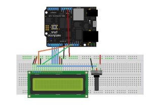
The following Fritzing diagram shows how the Netduino and the LCD are wired up:
The 10K potentiometer is used to control the contrast on the display. The wiring is as follows:
| LCD Pin | Description | Connection |
| 1 | Ground | Ground (taken from Netduino) |
| 2 | +5V | +5V (taken from Netduino) |
| 3 | Operating voltage for LCD | Centre pin of the 10K potentiometer |
| 4 | RS (High for data, Low for instructions) | Netduino digial pin 12 |
| 5 | R/W (High for read, Low for write) | Ground |
| 6 | Chip enable | Netduino digital pin 11 |
| 7 | DB0 – Data Bus line 0 | |
| 8 | DB1 – Data Bus line 1 | |
| 9 | DB2 – Data Bus line 2 | |
| 10 | DB3 – Data Bus line 3 | |
| 11 | DB4 – Data Bus line 4 | Netduino digital pin 2 |
| 12 | DB5 – Data Bus line 5 | Netduino digital pin 3 |
| 13 | DB6 – Data Bus line 6 | Netduino digital pin 4 |
| 14 | DB7 – Data Bus line 7 | Netduino digital pin 5 |
| 15 | Back light +ve | +5V |
| 16 | Back light ground | Ground |
Software
As previously mentioned, the main library for controlling this device can be found on Codplex. A little digging around in the examples gave me the code I needed to control the LCD. So leaving the examples behind I compiled the library into a DLL. Next step was to create a new project and add a reference to the DLL. I added the following code to the new project:
GpioLcdTransferProvider lcdProvider;
Lcd lcd;

lcdProvider = new GpioLcdTransferProvider(rs: Pins.GPIO_PIN_D12, enable: Pins.GPIO_PIN_D11, d4: Pins.GPIO_PIN_D2, d5: Pins.GPIO_PIN_D3, d6: Pins.GPIO_PIN_D4, d7: Pins.GPIO_PIN_D5);
lcd = new Lcd(lcdProvider);
lcd.Begin(columns: 16, lines: 2);
lcd.Write("Hello, world!");
while (true)
{
    lcd.SetCursorPosition(column: 0, row: 1);
    lcd.Write(Utility.GetMachineTime().ToString());
    Thread.Sleep(100);
}
Observations
For some reason, the initial run of the project did not function as expected. For a while I was sitting there looking at a blank display. Playing around with the potentiometer did not correct the problem. At some point I disconnected the backlight and again tried to change the contrast and a few dim letters appeared. A little more playing and I soon had a working display with the backlight working.
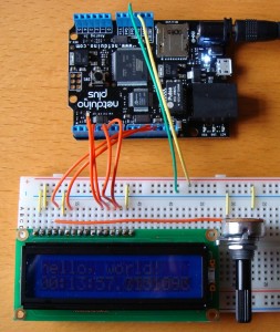
The image above shows the application running without the backlight connected. One further enhancement would be to use the transistor as a switch idea to allow the back light to be controlled from the software.
And the next step is to follow Szymon’s blog to reduce the number of pins required. But first a trip to Farnell’sweb site for some parts.
Tags: Electronics, Netduino
Saturday, January 15th, 2011 at 6:24 pm • Electronics, Netduino • RSS 2.0 feed Both comments and pings are currently closed.


