In this third and final post in this series I will finally connect the Netduino Plus to the external LED circuit I have been putting together over the past few days.
Objective
Use the push button on theNetduino Plusto toggle the state of the LED in the external LED circuit built here. The experiment should use software to change the state of the external LED.
Hardware Modifications
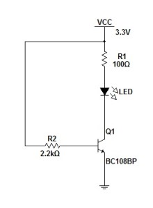
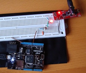
Much of the hard work (for me anyway as I’m a software engineer and not a hardware designer)hasalready been completed as the circuit in the previous post was designed to use a small current from a 3.3 V signal to turn a LED on or off. The only two changes to make are:
- Disconnect the base resistor R2 from the 3.3 V supply and connect to an appropriate digital output pin on theNetduino Plus.
- Couple the ground on the power supply on theNetduino Pluswith the ground on the external circuit.
Software
The software will have to provide the following functionality:
- Hold the current state of the LED
- Listen for the on board button being pressed and change the state of the LED.
Firstly, create a new project in Visual Studio using the Netduino Plus template (full instructions for installing the tools and templates can be found on the Netduino Plus web site. Make sure the project properties are set to deploy the application to the hardware over the USB port.
Next we need to declare some class level variables:
///
/// Determine if the LED is on (true) or off (false)
///
private static bool LEDState;
///
/// Output port used to control the external LED circuit.
///
private static OutputPort ExternalLED;
///
/// Button on the Netduino Plus.
///
private static InterruptPort OnBoardButton;
Next, we need to initialise the variables. In this case I am using pin D7 to control the LED. So we set up the port and then make sure the LED is turned off to start with.
ExternalLED = new OutputPort(Pins.GPIO_PIN_D7, false);
LEDState = false;
ExternalLED.Write(LEDState);
The final part of our main program instantiates the button and wires up the event handler:
OnBoardButton = new InterruptPort(Pins.ONBOARD_SW1, false, Port.ResistorMode.Disabled, Port.InterruptMode.InterruptEdgeLevelLow);
OnBoardButton.OnInterrupt += new NativeEventHandler(button_OnInterrupt);
//
//  Wait indefinetly.
//
Thread.Sleep(Timeout.Infinite);
The final bit of the puzzle is to write the logic for the interrupt handler:
private static void button_OnInterrupt(uint data1, uint data2, DateTime time)
{
    LEDState = !LEDState;
    ExternalLED.Write(LEDState);
    if ((OnBoardButton.Interrupt == Port.InterruptMode.InterruptEdgeLevelLow) || (OnBoardButton.Interrupt == Port.InterruptMode.InterruptEdgeLevelHigh))
    {
        OnBoardButton.ClearInterrupt();
    }
}
Connecting the hardware to the computer by USB and hit F5. Pressing the button on the Netduino Plus changes the state of the LED from off to on. Pressing the button again reverses this.
Observations
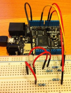
The final circuit looks like this:
One thing which did catch me out was the port interrupt mode settings. I started out setting the port (for the button) to InterruptEdgeLevelHigh and the system appeared to be generating an interrupt when the button was released. I pressed the button a few times and the state of the LED changed as I expected it to.
I decided it would be much more pleasing for the user if the LED state changed when the button was first pressed rather than having to wait for it to be released. So I changed the interrupt mode to InterruptEdgeLevelLow. Pressing the button did indeed change the state of the LED. However, subsequent presses of the button did not change the LED state.
Off to the .NET Microframework documentation, in particular the OnInterrupt event. Interestingly it notes the the ClearInterrupt method must be called if the input port is set to either InterruptEdgeLevelLow or InterruptEdgeLevelHigh. Interestingly in this application it was only required for one of these although the code above does call this method in both cases.
First project completed, I’m off to look for something more challenging.
C# Code for this project:NetduinoControllingExternalLED-Program.zip
