Simple LED Circuit
I suppose every journey starts with a single step, and often a small step at that. Relearning the skills of yesteryear will be no different. I’m slowly working myself up to controlling the LED from the Netduino Plus. On this basis I’ll be taking it steady and tackle this in three parts:
- Light a LED from a 3.3V power supply
- Use a transistor as a switch to control the LED circuit above (more here)
- Use the Netduino Plus to control the transistor/LED circuit
The reason for taking this slowly is the Netduino Plus can only supply a small amount of current and I’m taking care to draw as little current as possible whilst still having a usable project.
So step one, a simple LED circuit from a static power supply
The design is simple (I’m not taxing myself too much) and requires little more knowledge that that provided by the LED data sheet and Ohms Law. The task is to use a stable 3.3V power supply and use this to light up a red LED. Minor complication here, I don’t have the datasheet for the LED so I’m not sure how much current it will take. A quick search on Google provides a whole list of web sites with information on LEDs and the consensus of opinion is that modern red LEDs draw about 20mA max and have a typical voltage drop of around 2.5V (along with one comment that burning LEDs make a rather unpleasant smell).
Note 8 Jan 2011: Finally found the data sheet for the red LED being used and Vf = 2.5V and If = 20 mA.
Armed with this information I need to include a series resistor in the circuit to take the additional voltage drop and limit the current.
And for the calculations:
| Voltage drop across the resistor | = supply voltage – 2.5 |
| = 3.3 – 2.5 V | |
| = 0.8 V |
Working on the resistor we get the following:
| V | = I * R |
| R | = V / R |
| = 0.8 V / 20 mA | |
| = 40 ohms |
Now this resistor is not available as a standard component. The nearest ones are 39 ohms and 43 ohms. A quick look through my supply and I’ve got 33 ohms and 47 ohms. So I plump for the 47 ohms and the circuit becomes:

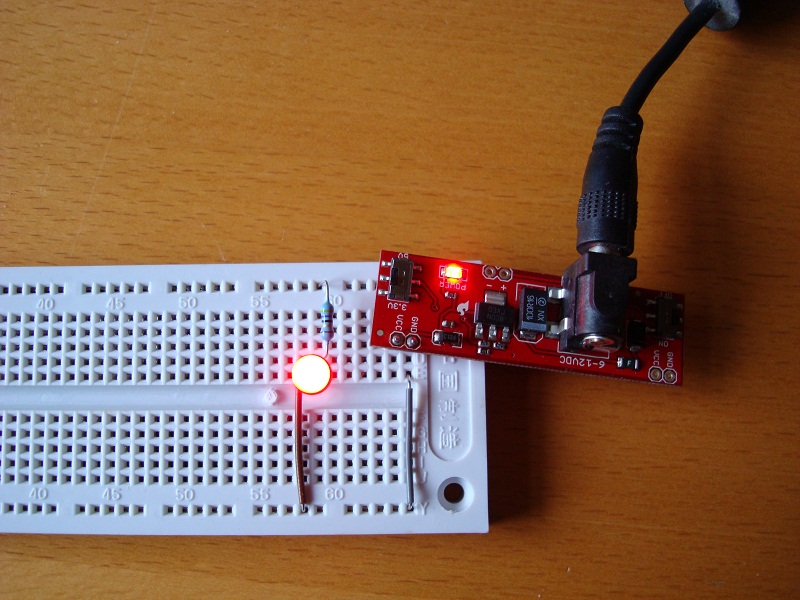
The power supply itself will come from a breadboard power supply stick from Cool Components.
Theory over, now for the application
First job is to solder a couple of male header row connectors to the power supply to make it easier to connect to the power supply to the breadboard. Next add the resistor and the LED and plug it all in.
The good news is it didn’t go bang and no hint of the smell of burning LEDs. In fact it worked, one glowing red LED.
A quick check with the multi-meter revealed that
- The power supply is in fact delivering 3.25V and not the rated 3.3V.
- The voltage drop over the series resistor was 1.25V which means the circuit is drawing 26mA and the voltage drop across the LED is in fact only 2V.
All in all a small and simple first step.
Tags: Electronics, LED
Saturday, January 1st, 2011 at 8:08 am • Electronics • RSS 2.0 feed Both comments and pings are currently closed.
