STM8S SPI Slave (Part 2)
Monday, November 19th, 2012In the previous post we looked at exchanging single bytes using SPI with a Netduino Plus acting as the SPI master device and the STM8S acting as a slave device. The code presented suffered from a few deficiencies:
- We could only exchange one byte and that was mirrored back to the master device
- The mirroring assumed that a byte received meant the STM8S was ready to send a byte back to the Netduino
In this post we will deal with both of these issues and also look at a new problem which can arise, namely synchronisation.
The aim of the code we will be developing is to receive a buffer of data and at the same time send a different buffer of data back to the master device.
Hardware
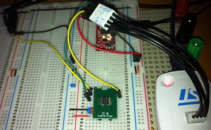
The hardware we will be using is identical to the initial SPI post. We will be using a few more bits from the registers in order to allow the STM8S application to determine the action we should be taking.
SPR_SR_OVR – Overflow Indicator
This bit will be set when the chip detects an overflow condition. This can happen if the bus speed is too high and the data is arriving at a rate which is faster than the Interrupt Service Routine (ISR) can process it.
SPI_SR_RXNE – Receive Buffer Not Empty
This bit indicates that the receive buffer is not empty and that data is ready to be read.
SPI_SR_TXE – Transmit Buffer Empty
This indicates that the SPI transmit buffer is empty and ready to receive another byte of data.
Netduino Plus Software
The software running on the Netduino Plus requires a small modification to allow it to send a buffer of data rather than a single byte. We will also take the opportunity to increase the SPI bus speed to 500KHz. The code running on the Netduino Plus becomes:
public class Program
{
	/// <summary>
	/// SPI object.
	/// </summary>
	private static SPI spi = null;

	/// <summary>
	/// Configuration of the SPI port.
	/// </summary>
	private static SPI.Configuration config = null;

	public static void Main()
	{
		config = new SPI.Configuration(SPI_mod: SPI.SPI_module.SPI1,        // Which SPI module to use?
									   ChipSelect_Port: Pins.GPIO_PIN_D10,  // Chip select pin.
									   ChipSelect_ActiveState: false,       // Chip select is low when SPI is active.
									   ChipSelect_SetupTime: 0,
									   ChipSelect_HoldTime: 0,
									   Clock_IdleState: false,              // Clock is active low.
									   Clock_Edge: true,                    // Sample on the rising edge.
									   Clock_RateKHz: 500);
		spi = new SPI(config);

		byte[] buffer = new byte[17];
		for (byte index = 0; index < 17; index++)
		{
			buffer[index] = index;
		}
		while (true)
		{
			for (byte counter = 0; counter < 255; counter++)
			{
				buffer[0] = counter;
				spi.Write(buffer);
				Thread.Sleep(200);
			}
		}
	}
}
As you can see, much of the code is the same as that presented in the previous post. This application will now transmit a 17 byte buffer to the SPI slave device. The first byte in the buffer will be a sequence number which will cycle through the values 0 to 254. The remaining bytes in the buffer will remain unchanged.
STM8S SPI Slave
The main changes we will be making are in the application running on the STM8S. In this case we need to deal with the following additional issues:
- Possible overflows due to the increased speed of the SPI bus
- Treating the receive and transmit scenarios as distinct cases
- Buffer overflows
The first thing we are going to need is somewhere to store the data. Looking at the Netduino Code we have defined the buffer size as 17 bytes. The corresponding declaration in the STM8S code look like this:
//--------------------------------------------------------------------------------
//
//  Miscellaneous constants
//
#define BUFFER_SIZE             17

//--------------------------------------------------------------------------------
//
//  Application global variables.
//
unsigned char _rxBuffer[BUFFER_SIZE];       // Buffer holding the received data.
unsigned char _txBuffer[BUFFER_SIZE];       // Buffer holding the data to send.
unsigned char *_rx;                         // Place to put the next byte received.
unsigned char *_tx;                         // Next byte to send.
int _rxCount;                               // Number of characters received.
int _txCount;                               // Number of characters sent.
We will also need to provide a mechanism to reset the SPI buffer pointers back to a default state ready to receive data:
//--------------------------------------------------------------------------------
//
//  Reset the SPI buffers and pointers to their default values.
//
void ResetSPIBuffers()
{
    SPI_DR = 0xff;
    _rxCount = 0;
    _txCount = 0;
    _rx = _rxBuffer;
    _tx = _txBuffer;
}
We also no longer have a single byte of data to output on the diagnostic pins. We therefore need to add a new diagnostic method to output the data we are receiving.
//--------------------------------------------------------------------------------
//
//  Bit bang a buffer of data on the diagnostic pins.
//
void BitBangBuffer(unsigned char *buffer, int size)
{
    for (int index = 0; index < size; index++)
    {
        BitBang(buffer[index]);
    }
}
The main method needs to be modified to take into account the changes we have made. The code becomes:
int main(void)
{
    //
    //  Initialise the system.
    //
    __disable_interrupt();
    InitialiseSystemClock();
    InitialiseSPIAsSlave();
    ResetSPIBuffers();
    for (unsigned char index = 0; index < BUFFER_SIZE; index++)
    {
        _txBuffer[index] = index + 100;
    }
    InitialiseOutputPorts();
    _status = SC_UNKNOWN;
    __enable_interrupt();
    //
    //  Main program loop.
    //
    while (1)
    {
        __wait_for_interrupt();
        if (_status == SC_RX_BUFFER_FULL)
        {
            BitBangBuffer(_rxBuffer, BUFFER_SIZE);
        }
        _status = SC_UNKNOWN;
    }
}
So far all of the code changes have been to support the initialisation and configuration of the system. The one area we have not touched upon is processing of the data which is being transmitted / received, namely the SPI ISR.
SPI Interrupt Service Routine
For the application we have built so far, the ISR must take into account three possible scenarios:
- Buffer Overflow
- Data received
- Data transmission buffer empty
The code will utilise the three status we identified earlier in order to determine which action to take. In each case we will do the following:
- SPI Overflow (SPI_SR_OVR is set)
Use the status codes to indicate an overflow has occurred and exit the ISR - Data Received (SPI_SR_RXNE is set)
Add the byte received to the buffer and update the buffer pointers. Set the status code to indicate that we have received some data. - Data transmission buffer empty (SPI_SR_TXNE is set)
Grab the next byte from the transmit buffer and send it. Update the transmit buffer pointers accordingly. - Deploy code to the Netduino Plus
At this point the application will start to run. We will be outputting a sequence of bytes followed by a 200ms pause. - Deploy the code to the STM8S
The application on the STM8S starts and waits for data to be received on the SPI bus. - Byte 16 transmitted by Netduino
The byte is received by the STM8S and put into the buffer at position 0. The buffer pointers are moved on to point to position 1. - Byte 17 is transmitted by the Netduino
The byte is received by the STM8S and put into the buffer at position 1. The buffer pointers are moved on to point to position 2. - Netduino enters the 200ms pause
The STM8S waits for the next byte - Byte 0 transmitted by Netduino
The byte is received by the STM8S and put into the buffer at position 2. The buffer pointers are moved on to point to position 3. - Falling Edge – Enable SPI
Resets the SPI buffers and the SPI registers ready for data transmission> Next, enable SPI. Finally, setup the chip select to detect a rising edge. - Rising Edge – Disable SPI
Disables SPI and sets the chip select to look for a falling edge.
We will be adopting a naïve buffering solution for this application. The buffers will be circular. The ISR can assume that there is space to save the next byte (i.e. we never overflow) as when we reach the end of the buffer we simply set the pointer back to the start again. The code for the ISR becomes:
#pragma vector = SPI_TXE_vector
__interrupt void SPI_IRQHandler(void)
{
    //
    //  Check for an overflow error.
    //
    if (SPI_SR_OVR)
    {
        (void) SPI_DR;                      // These two reads clear the overflow
        (void) SPI_SR;                      // error.
        _status = SC_OVERFLOW;
        OutputStatusCode(_status);
        return;
    }
    //
    //  Looks like we have a valid transmit/receive interrupt.
    //
    if (SPI_SR_RXNE)
    {
        //
        //  We have received some data.
        //
        *_rx = SPI_DR;              //  Read the byte we have received.
        _rx++;
        _rxCount++;
        if (_rxCount == BUFFER_SIZE)
        {
            _status = SC_RX_BUFFER_FULL;
            OutputStatusCode(_status);
            _rx = _rxBuffer;
            _rxCount = 0;
        }
    }
    if (SPI_SR_TXE)
    {
        //
        //  The master is ready to receive another byte.
        //
        SPI_DR = *_tx;
        _tx++;
        _txCount++;
        if (_txCount == BUFFER_SIZE)
        {
            OutputStatusCode(SC_TX_BUFFER_EMPTY);
            _tx = _txBuffer;
            _txCount = 0;
        }
    }
}
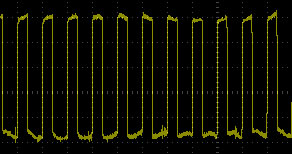
If we run these two applications and connect the logic analyser we are likely to see traces similar to the following:
This is not what we expected. In fact we expect to see something like the following:
The reason for this is the simple buffering and we have used and the fact that there we have not implemented a method for synchronising the two systems (Netduino and STM8S). The trace can be understood if we follow the deployment and startup cycles for each application. The sequence of events will proceed something like the following:
It is highly possible that when the application on the STM8S starts we will be part way through the transmission of a sequence of bytes by the Netduino. Let us make the assumption that this is the case and the Netduino is transmitting byte 16.
This sequence of events continues until the buffer on the STM8S is full. As you can see, the buffers started out unsynchronised and continue in this manner ad infinitum.
Interestingly, if you power down the two boards and then power them up simultaneously (or power up the STM8S and then the Netduino Plus) you will see the synchronised trace. This happens because the STM8S has been allowed to enter the receive mode before the Netduino Plus could start to send data.
Synchronising the Sender and Receiver
The key to the synchronisation is this case is to consider using an external signal to indicate the start of transmission of the first byte of the buffer. In theory this is what the NSS signal (chip select) is for. The STM8S does not provide a mechanism to detect the state change for the NSS line when operating in hardware mode (which is how the application has been operating so far). In order to resolve this we should consider converting the application to use software chip select mode.
Chip Select
The first thing to be considered is the port we will be using to detect the chip select signal. In this case we will be using Port B, pin 0. This port will need to be configured as an input with the interrupts enabled. The InitialisePorts method becomes:
void InitialisePorts()
{
    //
    //  Initialise Port D for debug output.
    //
    PD_ODR = 0;             //  All pins are turned off.
    PD_DDR = 0xff;          //  All pins are outputs.
    PD_CR1 = 0xff;          //  Push-Pull outputs.
    PD_CR2 = 0xff;          //  Output speeds upto 10 MHz.
    //
    //  Initialise Port B for input.
    //
    PB_ODR = 0;             //  Turn the outputs off.
    PB_DDR = 0;             //  All pins are inputs.
    PB_CR1 = 0xff;          //  All inputs have pull-ups enabled.
    PB_CR2 = 0xff;          //  Interrupts enabled on all pins.
    //
    //  Now set up the interrupt behaviour.
    //
    EXTI_CR1_PBIS = 2;      //  Port B interrupt on falling edge (initially).
}
One point to note about the above method is that we initially only detect the falling edge of the chip select signal. My first attempt at this code had both falling and rising edge detection in place. With this method enabled I found it difficult to detect which edge was causing the interrupt to be triggered. I therefore decided to initially detect only the falling edge. I would then add code to change the edge being detected to the ISR controlling the chip select. The code which detects the change of state for the chip select pin is as follows:
#pragma vector = 6
__interrupt void EXTI_PORTB_IRQHandler(void)
{
    if (EXTI_CR1_PBIS == 1)
    {
        //
        //  Transition from low to high disables SPI
        //
        SPI_CR1_SPE = 0;                        //  Disable SPI.
        SPI_CR2_SSI = 1;
        EXTI_CR1_PBIS = 2;                      //  Waiting for falling edge next.
        OutputStatusCode(SC_CS_RISING_EDGE);
    }
    else
    {
        //
        //  Transition from high to low selects this slave device.
        //
        EXTI_CR1_PBIS = 1;                      //  Waiting for rising edge next.
        ResetSPIBuffers();
        (void) SPI_DR;
        (void) SPI_SR;
        SPI_DR = *_tx++;                        //  Load the transmit with first byte.
        _txCount++;
        SPI_CR2_SSI = 0;
        SPI_CR1_MSTR = 0;
        SPI_CR1_SPE = 1;                        // Enable SPI.
        OutputStatusCode(SC_CS_FALLING_EDGE);
    }
}
This code performs two tasks:
You will also note a few lines outputting status information. These should be removed in production code but are left in here in order to aid debugging.
The final thing we need to do is to modify the initialisation of the SPI registers. These are small changes and merely change the system from hardware to software chip select. One key change is that we do not enable SPI here. This is left to the chip select interrupt handler. The new version of the InitialiseSPIAsSlave method becomes:
void InitialiseSPIAsSlave()
{
    SPI_CR1_SPE = 0;                    //  Disable SPI.
    SPI_CR1_CPOL = 0;                   //  Clock is low when idle.
    SPI_CR1_CPHA = 0;                   //  Sample the data on the rising edge.
    SPI_ICR_TXIE = 1;                   //  Enable the SPI TXE interrupt.
    SPI_ICR_RXIE = 1;                   //  Enable the SPI RXE interrupt.
    SPI_CR2_SSI = 0;                    //  This is SPI slave device.
    SPI_CR2_SSM = 1;                    //  Slave management performed by software.
}
Conclusion
This post shows how we can overcome the naïve data transmission method presented by the previous post and add the ability to buffer data and to store a buffered response. Running the final version of the code overcomes the synchronisation problem we encountered at the expense of performing out own chip select handling in software.
As usual, the source code for this application is available for download (STM8S SPI Slave and Netduino SPI Master).
Source Code Compatibility
| System | Compatible? |
| STM8S103F3 (Breadboard) | |
| Variable Lab Protomodule | |
| STM8S Discovery |

