RSS

Posts Tagged ‘Software Development’

Teensy 3.1 and Visual Micro

Tuesday, October 14th, 2014

September saw the end of an agonising few months (nearly a year in truth) working with a 32 x 32 LED matrix and smart LEDs (WS2811, Neopixels etc.). I’ve been trying to reliably control these LEDs with the STM32 Discovery board. It’s not that I cracked the problem with the STM32 but that I came across a cheap ready made solution to the problem, namely the Teensy 3.1. It has proved to be a painful reminder of something a software engineer should know, use libraries if you can. In the case of hardware prototyping the use of libraries also extends in part to the choice of hardware.

One of the main reasons I have resisted going down the route of using boards like the Teensy 3.1 is the Arduino IDE. I think that I have been spoiled by the richness of the Visual Studio IDE. Even IDES should as the IAR IDE for the STM8S leave something to be desired when you compare it to Visual Studio. This is the story of how I got the LEDs working and solved the IDE issue by using Visual Micro.

Problem Hardware

There are two pieces of hardware causing me problems at the moment:

  1. 32 x 32 LED Matrix
  2. 5mm Digital Addressable LEDs

These were purchased in the UK from Cool Components.

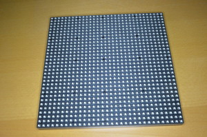
32 x 32 LED Matrix/Panel

The 32 x 32 LED matrix is often a component in larger displays.

LED Matrix

LED Matrix

The displays are easily chained together although the power requirements quickly increase. Each panel can consume up to 2A depending upon the number of LEDs illuminated as any time.

These boards are designed to be controlled by FPGAs allowing for high frame rates. Sparkfun and Adafruit have tutorials on running these boards and they have found that you can run a single panel at 16MHz (i.e. you can run it on an Arduino but only just). Running two or more panels requires more power, both RAM and processor speed.

Digitally Addressable LEDs

The LEDs in question use the WS2811 constant current IC to drive RGB LEDs. These controllers use their own one-wire protocol (not to be confused with the Dallas one-wire protocol) to determine the PWM characteristics of the red, green and blue components of the light output. Over the years these controllers have shown up in LED strings, LED strips and more recently as the Adafruit Neopixel and now as individual through hole LEDs.

The main problem I have found with these LEDs, or more specifically the controllers, is the one-wire protocol. This requires very precise timing and this is often difficult to obtain on the hobbyist microcontrollers without a lot of very precise control.

Solving the problem

I decided to solve this problem using the Teensy 3.1. The thing which makes the Teensy 3.1 very attractive for this type of project is the add-on board, the SmartMatrix Shield. This board allows you to connect a Teensy directly on to the IDC headers of the LED Matrix.

In addition to the hardware, the Teensy 3.1 library contains ports of the equivalent Arduino libraries for the 32 x 32 LED matrix as well as LEDs controlled by the WS2811.

Teensy 3.1

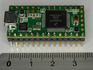
The Teensy has been through several iterations, the Teensy 3.1 being the latest at the time of writing. The board is small, only 35mm x 18mm, and I was not really prepared for how small it actually is!

TeensyAndRuler

Small does not mean low powered though, the board packs a Cortex-M4 processor, 256K flash and 64K RAM. The 72MHz processor can also be overclocked to over 90MHz. Other features include:

  • 34 Digital I/O (3.3V but 5V tolerant)
  • 21 analog inputs
  • 12 PWM
  • SPI, I2C, CAN bus
  • ARM DSP extension

The foot print of the board allows it to be easily added to a breadboard.

The Teensy 3.1 board is also supplied with it’s own libraries in the form of Teensyduino. This is an add-on for the Arduino IDE and is compatible with many of the Arduino libraries. The Arduino compatible libraries provide the ability to work with the LED matrix and the addressable LEDs mentioned above as well as a wide variety of other devices.

Software

As I have stated earlier, I am not really a fan of the Arduino IDE. Do not misinterpret me, it represents a great piece of work, however the amount of time and money Microsoft have poured into Visual Studio over the years means that Visual Studio really does take some beating. This is where Visual Micro comes in.

Visual Micro is a Visual Studio 2008-2013 add-in which allows the development of Arduino sketches within the Visual Studio framework. This gives you all the power of Visual Studio (code refactoring etc.) while still allowing the development of Arduino sketches. The add-in is free until the end of 2014 with the option to purchase the debugger support for a nominal fee.

The add-in supports a good number of boards out of the box including the Teensy 3.1.

Setup is simple and the documentation is really good. There are a few additional steps for the Teensy 3.1 but this is cover in the Tips for Teensy page.

Once configured it was a simple task to create a new Teensy 3.1 project using the Neopixel sketch template. A little code reformatting gives the following code:

#include <Adafruit_NeoPixel.h>

//
//	Parameter 1 = number of pixels in strip
//	Parameter 2 = pin number (most are valid)
//	Parameter 3 = pixel type flags, add together as needed:
//		NEO_RGB     Pixels are wired for RGB bitstream
//		NEO_GRB     Pixels are wired for GRB bitstream
//		NEO_KHZ400  400 KHz bitstream (e.g. FLORA pixels)
//		NEO_KHZ800  800 KHz bitstream (e.g. High Density LED strip)
//
Adafruit_NeoPixel strip = Adafruit_NeoPixel(60, 6, NEO_RGB + NEO_KHZ800);

//
//	Input a value 0 to 255 to get a color value.
//	The colours are a transition r - g - b - back to r.
//
uint32_t Wheel(byte WheelPos)
{
	if (WheelPos < 85)
	{
		return strip.Color(WheelPos * 3, 255 - WheelPos * 3, 0);
	}
	else if (WheelPos < 170)
	{
		WheelPos -= 85;
		return strip.Color(255 - WheelPos * 3, 0, WheelPos * 3);
	}
	else
	{
		WheelPos -= 170;
		return strip.Color(0, WheelPos * 3, 255 - WheelPos * 3);
	}
}

//
//	Fill the dots one after the other with a colour
//
void colorWipe(uint32_t c, uint8_t wait)
{
	for (uint16_t i = 0; i < strip.numPixels(); i++)
	{
		strip.setPixelColor(i, c);
		strip.show();
		delay(wait);
	}
}

//
//  Set all LEDs to the same colour.
//
void rainbow(uint8_t wait)
{
	uint16_t i, j;

	for (j = 0; j < 256; j++)
	{
		for (i = 0; i < strip.numPixels(); i++)
		{
			strip.setPixelColor(i, Wheel((i + j) & 255));
		}
		strip.show();
		delay(wait);
	}
}

//
//	Slightly different, this makes the rainbow equally distributed throughout
//
void rainbowCycle(uint8_t wait)
{
	uint16_t i, j;

	for (j = 0; j < 256 * 5; j++)
	{ // 5 cycles of all colors on wheel
		for (i = 0; i < strip.numPixels(); i++)
		{
			strip.setPixelColor(i, Wheel(((i * 256 / strip.numPixels()) + j) & 255));
		}
		strip.show();
		delay(wait);
	}
}

//
//	Executed once at startup to set up the board.
//
void setup()
{
	strip.begin();
	strip.show(); // Initialize all pixels to 'off'
}

//
//	The actual main program loop.
//
void loop()
{
	rainbow(20);
	rainbowCycle(20);
}

This code creates an Adafruit_NeoPixel object with the pixels connected to pin 6 of the Teensy 3.1.

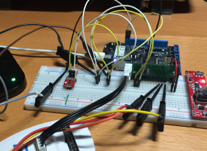
Connecting some LEDs top the Teensy and uploading the above code results in the following:

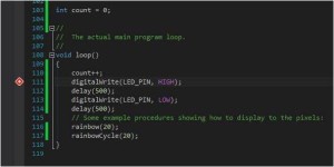
Modifying the code to add a counter will allow testing of the debugging features. The loop code is changed to have a counter variable to test the conditional breakpoint feature:

int count = 0;

//
//	The actual main program loop.
//
void loop()
{
	count++;
	digitalWrite(LED_PIN, HIGH);
	delay(500);
	digitalWrite(LED_PIN, LOW);
	delay(500);
	// Some example procedures showing how to display to the pixels:
	rainbow(20);
	rainbowCycle(20);
}

Adding a breakpoint after the counter increment and making the breakpoint conditional results in the following display:

Sample code

Sample Code With Breakpoint

Nothing too strange here, pretty much standard for Visual Studio. The breakpoint window shows the breakpoint and the condition:

Debugger Breakpoint Window

Debugger Breakpoint Window

Running the code brings up the debugger expression window:

Debugger Expression Window

Debugger Expression Window

The one thing which experienced users of Visual Studio will find unfamiliar is the way in which single stepping works. Unlike say Win32 development where single stepping takes you to the next line of code and then waits, with Visual Micro, single stepping runs the code to the next breakpoint.

Conclusion

Visual Studio is without doubt one of the best software development environments available. The addition of Visual Micro brings the power of Visual Studio to the Arduino world. Whilst the debugging features (single stepping) may a little unfamiliar to Visual Studio users they are not so strange as to be unusable.

Both the Teensy 3.1 and Visual Micro are a welcome addition to the development tools and it is highly likely that they will appear in future posts.

Using the Electric Imp

Monday, September 1st, 2014

A few weeks ago I acquired and Electric Imp as I was interested in how this could be used to prototype and connect a device to the Internet. Such a device would become part of the Internet of Things.

In order to investigate the possibility of using this device I decided to monitor the temperate of my office and log the data on the Internet.

Electric Imp

Electric Imp offers a starting point for hardware and software engineers wishing to develop for the Internet of Things. The simplest format for prototyping is probably the Imp001 and a breakout board. The Imp001 is an Electric Imp in SD format. The card is fully FCC certified and so offers a simple way of using a wireless network to connect a project to the Internet. The SD card contains a Cortex-M3 processor, 802.11b/g/n transceiver and antenna and once connected to a WiFi network with internet connectivity can be programmed using the cloud based development environment.

The Electric Imp is connected to a WiFi network using an application called BlinkUp. This application is a free download for iPhone and Android. The phone application takes details about the local WiFi network (name, password etc.) and sends this to the Imp001 by blinking the screen (hence the name BlinkUp) whilst the phone is held against the LED on the SD card.

Software for the Electric Imp is developed using the online IDE provided by Electric Imp. The development environment offers the ability to develop code which runs on the Electric Imp (Device code) itself as well as a component which runs in the cloud (Agent code). A user account is setup by following the link to the Log in page from the Electric Imp web site.

Sparkfun Data Logging Service

Sparkfun have recently started to provide a cloud based data logging service which is free to use for a limited amount of data. The system uses a circular 50 MByte data store for each data stream. Sign up is simple, just follow the Create link from the main page. The data streams can be both public and private. If the amount of data storage required is greater than 50MB or the application requires a greater level of privacy then the source is freely available for download by following the DFeploy link from the main page.

Once created, the data stream is accessed using public and private keys, the private keys allow data to be written to the data stream. The public key allows the public data stream to be viewed or data to be retrieved for use in say charting.

Temperature Logging

The principles involved in linking the local hardware to the Sparkfun cloud server will be illustrated by logging the local temperature using a temperature sensor and then sending the data to Sparkfun’s servers. The data will be retrieved and displayed on a web page.

Hardware

The bill of materials (BOM) for this project is as follows:

  1. Electric Imp (Imp001)
  2. Electric Imp Breakout board
  3. LM35 Temperature Sensor
  4. LED and current limiting resistor
  5. Connectors
  6. Breadboard and miscellaneous wire
  7. USB cable and power supply (your computer can act as a power supply if necessary)

Solder the connectors to the breakout board and insert the connectors into the breadboard.

Next, connect the current limiting resistor to Pin 9 on the breakout board and the LED. Connect the other leg of the LED through to ground.

Finally connect the LM35 temperature sensor to Vcc, Ground and the sensor output to Pin 2 of the breakout board.

Follow the instructions on the Electric Imp web site for downloading the BlinkUp software and configuring the Electric Imp. Configure the Imp and connect to the local WiFi network.

Electric Imp Software

The Electric Imp software is split into two components:

  1. Device code running on the Electric Imp hardware
  2. Agent code which runs on the Electric Imp cloud servers

The first step is to register with the Electric Imp web site for a developer account. Once completed you will be presented with the developer IDE.

To record the temperature the Electric Imp will record the temperature every 5 seconds. These readings will be summed and averaged over a one minute period. The average will sent to the Electric Imp servers, the average cleared and the whole process will restart. This will provide a continuous stream of temperature readings while the Imp is powered.

The Electric Imp servers will run Agent code which will listen for data/commands from the Electric Imp device code. The Agent on the server will then post the data to the Sparkfun server.

The code for the Device and the Agent is written in a C like language called Squirrel.

Device Code

The analog port on the Electric Imp returns a value in the range 0 to 65,535. The maximum value represents a voltage of 3.3V. The temperature sensor selected outputs 10mv per degree C. The maximum range of the values for this sensor is 0V to 1.55V given the operating range for the LM35.

The LED has been added to demonstrate when the board is taking a temperature reading. The LED will flash each time a reading is taken.

Firstly, some space in needed for the supporting variables:

//
//  Create a global variable to allow control of the LED.
//
led <- hardware.pin9;
//
//  Create a global variable for the temperature sensor.
//
temperatureSensor <- hardware.pin2;
// 
//  Configure led to be a digital output.
//
led.configure(DIGITAL_OUT);
//
//  Configure the temperature sensor to be an analog input.
//
temperatureSensor.configure(ANALOG_IN);
//
//  This name will be sent to the stream each update:
//
local impName = "Imp%20" + imp.getmacaddress();
//
//  Variables related to averaging the temperature.
//
readingCount <- 0;
readingSum <- 0.0;
// 
//  Create a global variables for the sensor readings.
//
temperature <- 0.0;
sensorValue <- 0;

Next, the main application loop (function), the first thing this should do is to turn on the LED to show that the application is active:

//
//  Main program loop.
//
function main()
{
    led.write(1);

Next, take the temperature sensor reading and convert to centigrade and add to the ongoing sum:

    sensorValue = temperatureSensor.read();
    temperature = ((sensorValue * 3.3) / 65535) * 100;
    readingCount++;
    readingSum += temperature;

Next, check if the number of readings has reached 12 (60 seconds). If we have 12 readings then take the average and send this to the Electric Imp Agent:

    if (readingCount == 12)
    {
        local average = readingSum / readingCount;
        server.log("Average temperature = " + average);
        local data = "";
        data = "Temperature=" + average;
        agent.send("postData", data);
        readingCount = 0;
        readingSum = 0.0;
    }

The server.log statement sends the logging information to the servers. This is not used anywhere, simply logged. The data is sent to the Agent in the agent.send(“postData”, data) statement.

Next, pause and then turn the LED off:

    imp.sleep(0.5);
    led.write(0);

The whole process should be repeated 4.5 seconds later (remember there is a 0.5 seconds pause above) to take readings every 5 seconds.

    //
    //  Schedule imp to wakeup and repeat.
    //
    imp.wakeup(4.5, main);
}

Finally the main loop should be executed:

//
//  Start the main program loop.
//
main();

Agent Code

The Agent code is responsible for listening for data from the device. The code used is actually provided by Sparkfun and is produced here more or less unaltered:

/*****************************************************************
Phant Imp (Agent)
Post data to SparkFun's data stream server system (phant) using
an Electric Imp
Jim Lindblom @ SparkFun Electronics
Original Creation Date: July 7, 2014

Description

Before uploading this sketch, there are a number of vars that need adjusting:
1. Phant Stuff: Fill in your data stream's public, private, and 
data keys before uploading!

This code is beerware; if you see me (or any other SparkFun 
employee) at the local, and you've found our code helpful, please 
buy us a round!

Distributed as-is; no warranty is given.
*****************************************************************/

//
//  Phant Stuff configuration information.
//
local publicKey = "Your-Public-Key-Goes-Here";      // Your Phant public key
local privateKey = "Your-Private-Key-Goes-Here";    // Your Phant private key
local phantServer = "data.sparkfun.com";            // Your Phant server, base URL, no HTTP

//
//  When the agent receives a "postData" string from the device, use the
//  dataString string to construct a HTTP POST, and send it to the server.
//
device.on("postData", function(dataString)
    {
        server.log("Sending " + dataString); // Print a debug message
        //
        //  Construct the base URL: https://data.sparkfun.com/input/PUBLIC_KEY:
        //
        local phantURL = "https://" +  phantServer + "/input/" + publicKey;
        //
        //  Construct the headers: e.g. "Phant-Private-Key: PRIVATE_KEY"
        //
        local phantHeaders = {"Phant-Private-Key": privateKey, "connection": "close"};
        //
        //  Send the POST to phantURL, with phantHeaders, and dataString data.
        //
        local request = http.post(phantURL, phantHeaders, dataString);
        //
        //  Get the response from the server, and send it out the debug window:
        //
        local response = request.sendsync();
        server.log("Phant response: " + response.body);
    }
);

The code is clearly commented and self explanatory.

Results

Building the above in the IDE should deploy the device code to the Electric Imp should result in the temperature being collected by the device, sent to the Electric Imp server and then from there on to Sparkfun’s servers. The data can be viewed in it’s raw form by browsing to your data stream using a URL such as: https://data.sparkfun.com/streams/Your-Public-Key-Here. This URL will have been supplied on the account creation page for the Sparkfun data service.

The data can also be retrieved using Javascript:

<!DOCTYPE html>
<html>
  <head>
    <!-- EXTERNAL LIBS-->
    <script src="https://ajax.googleapis.com/ajax/libs/jquery/1.11.1/jquery.min.js"></script>
    <script src="https://www.google.com/jsapi"></script>

    <!-- EXAMPLE SCRIPT -->
    <script>

      // onload callback
      function drawChart() {

        var public_key = 'Your-Public-Key-Here';

        // JSONP request
        var jsonData = $.ajax({
          url: 'https://data.sparkfun.com/output/' + public_key + '.json',
          data: {page: 1},
          dataType: 'jsonp',
        }).done(function (results) {

          var data = new google.visualization.DataTable();

          data.addColumn('datetime', 'Time');
          data.addColumn('number', 'Temperature');

          $.each(results, function (i, row) {
            data.addRow([
              (new Date(row.timestamp)),
              parseFloat(row.Temperature),
            ]);
          });

          var chart = new google.visualization.LineChart($('#chart').get(0));

          chart.draw(data, {
            title: 'Room Temperature', height: 500, is3D: true
          });

        });

      }

      // load chart lib
      google.load('visualization', '1', {
        packages: ['corechart']
      });

      // call drawChart once google charts is loaded
      google.setOnLoadCallback(drawChart);

    </script>
  </head>
  <body>
    <div id="chart" style="width: 100%;"></div>
  </body>
</html>

The above uses Google’s chart API to generate a chart from the data stored in the Sparkfun servers (thanks for Sparkfun for the code). Save the above page to a web server and browse to the page and you will see something like the following:

Room Temperature Chart

Room Temperature Chart

The chart shows the fall and rise in temperature in a room over a period of 48 hours.

Conclusion

The Electric Imp offers a simple method for connecting a device to the Electric Imp servers on the Internet. The Agent code can then pass this data on to services provided by additional third parties.

The device options used here would increase the cost of any device produced but as a proof of concept they offer a simple and convenient way of demonstrating how a device can interact with the outside world over the Internet. This example took less than 3 hours to research, build and complete – good going considering how complex this would be if this were completed in a conventional manner (Arduino, WiFly shield etc.).

Intel Galileo – First Impressions

Thursday, August 21st, 2014

Yesterday I received my Intel Galileo rev 1 board. I know the rev 2 board is available but recently the Windows on Devices program have release the necessary firmware etc to upgrade a Galileo rev 1 board to enable it to run Windows.

See the end of this article for an update added on 6th Sept 2014.

Upgrading the Firmware

The first step was to check athe firmware and upgrade it if necessary. In my case it was necessary. Intel provide a comprehensive set of instructions on how to do this. The upgrade process took about 10 minutes.

Creating a Windows SD Card

The next step is to write Windows to a micro SD card. This step of the process took the longest to complete, about 25-30 minutes.

Booting to Windows

The next step is to verify that Windows has loaded correctly. Insert the card, power on and then waiting for 2 minutes for Windows to boot. If successful you should be able to telnet to the device. I used PTTYPortable to do this and was presented with the login request.

Testing the Board

One of the first tests I normally perform is to deploy a Blinky application to the board. Once I am happy that I can deploy applications to the board I speed up Blinky by removing any code which would cause a pause. The result should be an indicator of the performance of the board and the software. So let’s give it a go.

The Galileo board offers two methods for deploying Blinky to the board:

  1. Arduino UI
  2. Visual Studio Windows application

The first method uses the board without the Windows SD card image, the second deploys a Windows application to the SD card and runs as a Windows application.

Our starting point for the tests will be the standard Blink application:

/*
  Blink
  Turns on an LED on for one second, then off for one second, repeatedly.
 
  This example code is in the public domain.
*/
 
// Pin 13 has an LED connected on most Arduino boards.
// give it a name:
int led = 13;

// the setup routine runs once when you press reset:
void setup()
{                
    // initialize the digital pin as an output.
    pinMode(led, OUTPUT);     
}

// the loop routine runs over and over again forever:
void loop()
{
    digitalWrite(led, HIGH);   // turn the LED on (HIGH is the voltage level)
    delay(1000);               // wait for a second
    digitalWrite(led, LOW);    // turn the LED off by making the voltage LOW
    delay(1000);               // wait for a second
}

Arduino UI

Using this application in the Arduino UI for the Galileo is simple. In fact the application is one of the samples (File -> Examples -> 01.Basics -> Blink). Loading this sketch and deploying to the Galileo starts the on board LED blinking at a steadily at 1 Hz.

Visual Studio Windows Application

Microsoft have provided a Wiring API for use in Visual Studio. This allows access to the “Arduino” hardware from a Windows application. An equivalent Windows version of the same application is:

#include "stdafx.h"
#include "arduino.h"

int _tmain(int argc, _TCHAR* argv[])
{
    return RunArduinoSketch();
}

int led = 13;  // This is the pin the LED is attached to.

void setup()
{
    pinMode(led, OUTPUT); // Configure the pin for OUTPUT so you can turn on the LED.
}

// the loop routine runs over and over again forever:
void loop()
{
    digitalWrite(led, LOW);    // turn the LED off by making the voltage LOW
    Log(L"LED OFF\n");
    delay(1000);               // wait for a second
    digitalWrite(led, HIGH);    // turn the LED on by making the voltage HIGH
    Log(L"LED ON\n");
    delay(1000);               // wait for a second
}

Much of the application looks the same as the Arduino application. The main differences are the addition of the _tmain method and the Log statement. The _tmain method acts as the entry point for the application and provides a method for running an Arduino sketch (as above) or some other program logic.

The Log statements generate debug information which is displayed in Visual Studio’s Output window.

Deploying this application to the board results in… NOTHING!

Digging a little deeper into the examples section of the web site reveals the On Board LED example:

// Main.cpp : Defines the entry point for the console application.
//

#include "stdafx.h"
#include "arduino.h"

int _tmain(int argc, _TCHAR* argv[])
{
    return RunArduinoSketch();
}

//This application flashes the on board LED of the Galileo board by calling GPIO functions directly in the embprpusr.dll instead of using the Arduino layer.

ULONG state = LOW; // keeps track of the state of the on-board LED

void setup()
{
    GpioSetDir(LED_BUILTIN, OUTPUT); // Sets the pin to output
}

void loop()
{
    if (HIGH == state)
    {
	    state = LOW;
	} 
    else
    {
	    state = HIGH;
	}
    GpioWrite(LED_BUILTIN, state); // Writes to the pin, setting its value either HIGH (on) or LOW (off)
    Log(L"LED %s\n", (HIGH == state ? L"ON" : L"OFF"));
    Sleep(1000);
}

Compiling and deploying this application to the board results in the steady flashing of the on board LED.

Reverting to the previous sample and hooking up an oscilloscope reveals that pin 13 is indeed being toggled at 1 Hz it is just not connected directly to the on board LED.

How Fast Can We Go?

Now to find out how fast the board will actually run. Starting with the Arduino example, remove the delay statements, recompile and deploy to the board. Doing this resulted in a square wave with a 50% duty cycle and a frequency of 221Hz. That’s right Hz, not KHz!

Removing the delay and logging statements and deploying the Windows application results in a square wave. This time a 60Hz square wave with a 30% duty cycle is displayed on the oscilloscope.

There must be something wrong. Surely this board with a 400MHz processor should run faster than this.

What About the Netduino?

The Netduino has always had one issue when compared with Arduino and other similar board. Namely it is running interpreted code which is not real time due to the nature of the .NET Microframework and the way the framework runs. I have performed similar tests and I was convinced that it was faster. Only one way to find out, deploy some code to the Netduino Plus 2. This board runs the .NET Microframework on the STM32 family of microcontrollers at 168 MHz. The equivalent code to the two examples above is:

using Microsoft.SPOT.Hardware;
using SecretLabs.NETMF.Hardware.Netduino;

namespace NetduinoPlus2
{
    public class Program
    {
        public static void Main()
        {
            OutputPort dp = new OutputPort(Pins.GPIO_PIN_D13, false);
            while (true)
            {
                dp.Write(!dp.Read());
            }
        }
    }
}

Deploying this to the Netduino PLus 2 and hooking up the oscilloscope results in a square wave with a 50% duty cycle at 17.8 KHz.

Much faster than the Galileo board.

Update 6th Sept 2014

I have been looking through the schematic for the Galileo Rev 1 board and found that not all of the GPIO pins are connected through the CY8C9540A chip but are in fact connected directly top the Quark processor. These GPIOs should be capable of higher speeds. A quick test shows that these pins (Digital 2, 3 & 10) can all generate a 1.16 KHz square wave for an application compiled in debug mode. Compiling the same applications in release more and running the application on the Galileo increases the frequency from 1.16 KHz to 1.27 KHz.

Conclusion

I’ve only had this board for a few hours but I have deployed a few of the examples. The raw GPIO speed appears lower than the interpreted .NET Microframework equivalent. The Galileo has access to a network port with easy access to the Arduino Wiring API but then so does the .NET Microframework.

Some further investigation is required I believe.

Window Watchdog

Saturday, July 5th, 2014

Window watchdogs provide a mechanism for detecting software failures in two ways, firstly an early reset of the watchdog and secondly a failure to reset the watchdog in time. In this post we investigate how the window watchdog can be use and illustrate with some examples.

Hardware

Window Watchdog Control Register – WWDG_CR

This register has two components, the timer counter and the enable bit (WWDG_CR_WDGA – see below). The microcontroller will be reset when one of two possible conditions:

  • The counter switches from 0x40 to 0x3f (i.e. bit 6 in the counter changes from 1 to 0)
  • The counter is reset when the counter value is greater than the watchdog window register

Writing 0 to bit 6 will cause the microcontroller to be reset immediately.

Assuming that WWDG_WR contains the default reset value then the time out period (in milliseconds) is defined as follows:

tWWDG = tCPU * 12288 * (WWDG_CR & 0x3f)

where tCPU = 1 / fmaster

On the STM8S running at 16MHz a value of 0x40 represents one count which is equal to 0.768ms. So at 16MHz the time out period is:

tWWDG = 0.768 * (WWDG_CR & 0x3f)

Window Watchdog Enable Register – WWDG_CR_WDGA

Switch the Window Watchdog on (set to 1) or off (set to 0).

Window Watchdog Window Register – WWDG_WR

This register defines a time period where the watchdog counter should not be reset. If the counter (WWDG_CR) is reset when the counter value is greater than the value in this register the microcontroller will be reset. This can be illustrated as follows:

Watchdog Sequence

Watchdog Sequence

We can calculate the value of tWindowStart and ttimeout as follows (assuming a 16MHz clock):

tWindowStart = 0.768 * ((WWDG_CRinitial & 0x3f) – WWDG_WR)

and

ttimeout = 0.768 * (WWDG_CR & 0x3f)

where WWDG_CRinitial is the initial value in the WWDG_CR register.

The default reset value for this register is 0x7f which means that the counter can be reset at any time. In this case, a reset will only be generated if the counter drops below 0x40.

One important point to note is that when the window register is used the value written to the counter (WWDG_CR) must be between 0xc0 and 0x7f. This causes the counter to be reset and the counter value to be reset simultaneously.

Software

The function of the Window Watchdog will be illustrated using the following three examples:

  • WWDG_CR not reset
  • WWDG_CR reset outside the reset window
  • WWDG_CR reset inside the reset window

The first thing we need to do is add some code which will be used in all of the examples.

Common Code

Firstly, lets add the code which will be common to all of the examples:

//
//  This program demonstrates how to use the Window Watchdog on the STM8S
//  microcontroller.
//
//  This software is provided under the CC BY-SA 3.0 licence.  A
//  copy of this licence can be found at:
//
//  http://creativecommons.org/licenses/by-sa/3.0/legalcode
//
#include <iostm8S105c6.h>
#include <intrinsics.h>

//--------------------------------------------------------------------------------
//
//  Setup the system clock to run at 16MHz using the internal oscillator.
//
void InitialiseSystemClock()
{
    CLK_ICKR = 0;                       //  Reset the Internal Clock Register.
    CLK_ICKR_HSIEN = 1;                 //  Enable the HSI.
    CLK_ECKR = 0;                       //  Disable the external clock.
    while (CLK_ICKR_HSIRDY == 0);       //  Wait for the HSI to be ready for use.
    CLK_CKDIVR = 0;                     //  Ensure the clocks are running at full speed.
    CLK_PCKENR1 = 0xff;                 //  Enable all peripheral clocks.
    CLK_PCKENR2 = 0xff;                 //  Ditto.
    CLK_CCOR = 0;                       //  Turn off CCO.
    CLK_HSITRIMR = 0;                   //  Turn off any HSIU trimming.
    CLK_SWIMCCR = 0;                    //  Set SWIM to run at clock / 2.
    CLK_SWR = 0xe1;                     //  Use HSI as the clock source.
    CLK_SWCR = 0;                       //  Reset the clock switch control register.
    CLK_SWCR_SWEN = 1;                  //  Enable switching.
    while (CLK_SWCR_SWBSY != 0);        //  Pause while the clock switch is busy.
}

//--------------------------------------------------------------------------------
//
//  Initialise the ports.
//
//  Configure all of Port D for output.
//
void InitialisePorts()
{
    PD_ODR = 0;             //  All pins are turned off.
    PD_DDR = 0xff;          //  All pins are outputs.
    PD_CR1 = 0xff;          //  Push-Pull outputs.
    PD_CR2 = 0xff;          //  Output speeds up to 10 MHz.
}

This code has been used many times in The Way of the Register series of posts. It simply sets the system clock to the high speed internal clock and configures Port D for output.

Example 1 – Continuous Reset

This example sets the Windows Watchdog running and then waits for the watchdog to trigger the system reset. We indicate that the application is running by generating a pulse on Port D, pin 2.

//--------------------------------------------------------------------------------
//
//  Initialise the Windows Watchdog.
//
void InitialiseWWDG()
{
    PD_ODR_ODR2 = 1;
    __no_operation();
    __no_operation();
    __no_operation();
    __no_operation();
    PD_ODR_ODR2 = 0;
    WWDG_CR = 0xc0;
}

The __no_operation() instruction in the above code allow the pulse to stabilise on the pin.

The WWDG_CR is set to 0xc0 to both set the value in the counter and enable the watchdog at the same time. This sets bit 6 in the counter to 11 and the remaining bits to 0 (i.e. the counter is set to 0x40). The effect of this is that the first down count event will cause bit 6 to be cleared and the counter to be set to 0x3f. This will trigger the reset event.

The main program simply sets everything up and then “pauses” by simply waiting for an interrupt:

//--------------------------------------------------------------------------------
//
//  Main program loop.
//
int main()
{
    //
    //  Initialise the system.
    //
    __disable_interrupt();
    InitialiseSystemClock();
    InitialisePorts();
    InitialiseWWDG();
    __enable_interrupt();
    //
    //  Main program loop.
    //
    while (1)
    {
        __wait_for_interrupt();
    }
}

If we run this application and connect PD2 and NRST to the oscilloscope we see the following trace:

Initial continuous reset

Initial continuous reset

The yellow trace shows the reset line being pulled low and gradually returning to high. The drop shows where the watchdog has caused the reset pin to be pulled low and the microcontroller to be reset. The blue trace shows the pulse on PD2. If we measure the time difference between the pulse on PD2 and the time that the reset pin is pulled low we find that this is 770uS. This is very close to the time for one count, 768uS.

To verify this we can change the value in the counter to say 0x48. In this case we should see the watchdog running for 9 counts and the system running for 6.912mS. Changing WWDG_CR = 0xc0 to WWDG_CR = 0xc8 gives the following output on the oscilloscope:

Continuous reset

Continuous reset

Measuring the time difference we get a value of 6.9mS.

Example 2 – Reset Outside Watchdog Window

Using the above code as a starting point we will look at the effects of the watch dog window register (WWDG_WR). This defines when the application is allowed to change the value in the counter. The first task is to change the initial value in the control register to 0xc1 and verify that we get a rest every 1.54ms (2 x timer period). So change the InitialiseWWDG method to the following:

void InitialiseWWDG()
{
    PD_ODR_ODR2 = 1;
    __no_operation();
    __no_operation();
    __no_operation();
    __no_operation();
    PD_ODR_ODR2 = 0;
    WWDG_CR = 0xc1;
}

Running this application on the STM8S Discovery board results in the following traces:

Reset Outside window

Reset Outside window

Now we have two counts (1.54mS) in order to change the value in the control register. First task is to modify the InitialiseWWDG method to define the window. We will define this to be 0x40:

void InitialiseWWDG()
{
    PD_ODR_ODR2 = 1;
    __no_operation();
    __no_operation();
    __no_operation();
    __no_operation();
    PD_ODR_ODR2 = 0;
    WWDG_CR = 0xc1;
    WWDG_WR = 0x40;
}

This means that for the first 768uS the control register should not be changed. If the register is changed during this period a reset will be triggered. To demonstrate this we will change the value in the control register immediately after the microcontroller has been initialised:

int main()
{
    //
    //  Initialise the system.
    //
    __disable_interrupt();
    InitialiseSystemClock();
    InitialisePorts();
    InitialiseWWDG();
    __enable_interrupt();
    //
    //  Main program loop.
    //
    while (1)
    {
        WWDG_CR = 0xc1;             //  Trigger a reset.
        __wait_for_interrupt();
    }
}

Deploying this application to the microcontroller results in the following trace on the oscilloscope:

Watchdog immediate reset

Watchdog immediate reset

As you can see, the system is reset almost immediately (there is virtually no time between the pulse on PD2 and the reset line being pulled low).

Example 3 – Reset Within the Watchdog Window

Starting with the common code we initialise the Window Watchdog with the following method:

//--------------------------------------------------------------------------------
//
//  Initialise the Windows Watchdog.
//
void InitialiseWWDG()
{
    WWDG_CR = 0x5b;         //  Approx 70ms total window.
    WWDG_WR = 0x4c;         //  Approx 11.52ms window where cannot reset
    WWDG_CR_WDGA = 1;       //  Enable the watchdog.
}

This code defines a period of 11.52ms where we cannot reset the window watchdog counter followed by a period of 9.216ms during which the watchdog counter must be reset in order to prevent the microcontroller from being reset.

A simple main application loop would look something like this:

//--------------------------------------------------------------------------------
//
//  Main program loop.
//
int main()
{
    //
    //  Initialise the system.
    //
    __disable_interrupt();
    InitialiseSystemClock();
    InitialisePorts();
    PD_ODR_ODR4 = 1;
    __no_operation();
    PD_ODR_ODR4 = 0;
    InitialiseWWDG();
    __enable_interrupt();
    //
    //  Main program loop.
    //
    while (1)
    {
        unsigned char counter = (unsigned char) WWDG_CR;
        if ((counter & 0x7f) < WWDG_WR)
        {
            WWDG_CR = 0xdb;     //  Reset the Window Watchdog counter.
            PD_ODR_ODR2 = !PD_ODR_ODR2;
        }
        //
        //  Do something here.
        //
    }
}

The initial pulse on PD4 indicates that the application has started. We can use this to detect the reset of the microcontroller. In this trivial application the main program loop simply checks to see if the current value of the counter is less than the value in WWDG_WR. If the counter is less than WWDG_WR then the system write a new value into the counter. The value written is 0x5b anded with 0x80, this brings the reset value into the value range (0xc0 – 0xff).

This application also pulses PD2 to indicate that the watchdog counter has been reset.

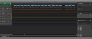
Deploying this application and hooking up the Saleae logic analyser gives the following trace:

Window watchdog initial trace

Window watchdog initial trace

As you can see, there is an initial pulse showing that the board is reset (top trace) and then a series of pulses showing that the counter is being reset (lower trace). Each up/down transition represents a watchdog counter reset.

This is a relatively trivial example so let’s spice this up and add in a timer.

To the code above add the following code:

//--------------------------------------------------------------------------------
//
//  Setup Timer 2 to generate a 12.5ms interrupt.
//
void SetupTimer2()
{
    TIM2_PSCR = 0x02;       //  Prescaler = 4.
    TIM2_ARRH = 0xc3;       //  High byte of 50,000.
    TIM2_ARRL = 0x50;       //  Low byte of 50,000.
    TIM2_IER_UIE = 1;       //  Enable the update interrupts.
    TIM2_CR1_CEN = 1;       //  Finally enable the timer.
}

This method will set up timer 2 to generate an interrupt every 12.5ms.

Adding the following will catch the interrupt:

//--------------------------------------------------------------------------------
//
//  Timer 2 Overflow handler.
//
#pragma vector = TIM2_OVR_UIF_vector
__interrupt void TIM2_UPD_OVF_IRQHandler(void)
{
    if (_firstTime)
    {
        InitialiseWWDG();
        _firstTime = 0;
    }
    else
    {
        unsigned char counter = (unsigned char) WWDG_CR;
        unsigned char window = WWDG_WR;
        BitBangByte(counter & 0x7f);
        BitBangByte(window);
        WWDG_CR = 0xdb;     //  Reset the Window Watchdog counter.
        counter = (unsigned char) WWDG_CR;
        BitBangByte(counter);
    }
    PD_ODR_ODR2 = !PD_ODR_ODR2;
    TIM2_SR1_UIF = 0;       //  Reset the interrupt otherwise it will fire again straight away.
}

The interrupt will, on first invocation, initialise the window watchdog. Subsequent invocations will output the values of the registers and reset the window watchdog.

We need some code to bit bang the register values:

#define SR_CLOCK            PD_ODR_ODR5
#define SR_DATA             PD_ODR_ODR3

//
//  BitBang the data through the GPIO ports.
//
void BitBangByte(unsigned char b)
{
    //
    //  Initialise the clock and data lines into known states.
    //
    SR_DATA = 0;                    //  Set the data line low.
    SR_CLOCK = 0;                   //  Set the clock low.
    //
    //  Output the data.
    //
    for (int index = 7; index >= 0; index--)
    {
        SR_DATA = ((b >> index) & 0x01);
        SR_CLOCK = 1;               //  Send a clock pulse.
        __no_operation();
        SR_CLOCK = 0;
    }
    //
    //  Set the clock and data lines into a known state.
    //
    SR_CLOCK = 0;                   //  Set the clock low.
    SR_DATA = 0;
}

The main program loop needs to be modified to set up the timer and registers etc. So replace the main program loop with the following:

//--------------------------------------------------------------------------------
//
//  Main program loop.
//
int main()
{
    //
    //  Initialise the system.
    //
    __disable_interrupt();
    InitialiseSystemClock();
    InitialisePorts();
    PD_ODR_ODR4 = 1;
    __no_operation();
    PD_ODR_ODR4 = 0;
    SetupTimer2();
    InitialiseWWDG();
    __enable_interrupt();
    //
    //  Main program loop.
    //
    while (1)
    {
        __wait_for_interrupt();
    }
}

Deploying and running this application gives the following output on the Saleae logic analyser:

Window watchdog full trace

Window watchdog full trace

Zooming in produces the following

Window watchdog zoomed in

Window watchdog zoomed in

Starting with the top trace and descending we can see the following values:

  • Reset pulse
  • Timer 2 interrupt triggers (up/down transitions)
  • Data (register values)
  • Clock signal

The decoded register values can be seen above the data trace. The first value is the current value of the counter. The second value is the value in the window watchdog register and the final value is the new value in the counter register.

Conclusion

The Window Watchdog provides a mechanism for the developer to detect software faults similar to the Independent Watchdog but further constrains the developer by defining a window where a counter reset by the application is not allowed.

STM8S Beep Function

Tuesday, July 1st, 2014

The beep function uses the 128 KHz LSI to generate a beep signal on the beep pin of the STM8S. This post demonstrates how to use this function.

Hardware

The signal is output on the beep pin. On the STM8S discovery board this is an alternative function on PD4 (port D, pin 4).

Setting the Alternative Function

The alternative functions are assigned to a pin by reprogramming the option bytes. This can be performed using the ST Visual Programmer. Start this application and read the option bytes from the STM8S:

Reading the options bytes using ST Visual Developer

Reading the options bytes using ST Visual Developer

  1. Select the STM8S model. On the STM8S Discovery board this is STM8S105C6
  2. Select the OPTION BYTE tab
  3. Read the option bytes from the microcontroller
  4. Check the value of the AFR7 bit

AFR7 needs to be set to Port D4 Alternative Function = BEEP on the STM8S Discovery board. This may be different on your STM8S so check the documentation for your microcontroller. To set the alternative function to beep:

Writing new options bytes using ST Visual Developer

Writing new options bytes using ST Visual Developer

  1. Select Port D4 Alternative Function = BEEP from the list of values in the alternative functions
  2. Write the option bytes back to the microcontroller

The beep function should now be assigned to PD4.

Registers

The beep function is controlled by three registers:

  • BEEP_CSR_BEEPSEL
  • BEEP_CSR_BEEPDIV
  • BEEP_CSR_BEEPEN

Beep Selection – BEEP_CSR_BEEPSEL

These bits set the multiplier for the Beep Divider.

BEEP_CSR_BEEPSELFrequency (KHz)
0fLSI / (8 * BEEPDIV)
1fLSI / (4 * BEEPDIV)
2 or 3fLSI / (2 * BEEPDIV)

Beep Divider – BEEP_CSR_BEEPDIV

Value for the prescalar divider.

BEEPDIV = 2 + BEEP_CSR_BEEPDIV

The documentation states that this should not be left set to the reset value (0x1f) and the value should be in the range 0 – 0x1e.

Beep Enable – BEEP_CSR_BEEPEN

Enable the beep function by setting this to 1, disable by setting this to 0.

Software

We start by providing a method for resetting the system clock to use the HSI:

//
//  This program demonstrates how to use the beep function on the STM8S 
//  microcontroller.
//
//  This software is provided under the CC BY-SA 3.0 licence.  A
//  copy of this licence can be found at:
//
//  http://creativecommons.org/licenses/by-sa/3.0/legalcode
//
#include <iostm8S105c6.h>
#include <intrinsics.h>

//--------------------------------------------------------------------------------
//
//  Setup the system clock to run at 16MHz using the internal oscillator.
//
void InitialiseSystemClock()
{
    CLK_ICKR = 0;                       //  Reset the Internal Clock Register.
    CLK_ICKR_HSIEN = 1;                 //  Enable the HSI.
    CLK_ECKR = 0;                       //  Disable the external clock.
    while (CLK_ICKR_HSIRDY == 0);       //  Wait for the HSI to be ready for use.
    CLK_CKDIVR = 0;                     //  Ensure the clocks are running at full speed.
    CLK_PCKENR1 = 0xff;                 //  Enable all peripheral clocks.
    CLK_PCKENR2 = 0xff;                 //  Ditto.
    CLK_CCOR = 0;                       //  Turn off CCO.
    CLK_HSITRIMR = 0;                   //  Turn off any HSIU trimming.
    CLK_SWIMCCR = 0;                    //  Set SWIM to run at clock / 2.
    CLK_SWR = 0xe1;                     //  Use HSI as the clock source.
    CLK_SWCR = 0;                       //  Reset the clock switch control register.
    CLK_SWCR_SWEN = 1;                  //  Enable switching.
    while (CLK_SWCR_SWBSY != 0);        //  Pause while the clock switch is busy.
}

The next task is to configure the beep function:

//--------------------------------------------------------------------------------
//
//  Initialise the Beep function.
//
void InitialiseBeep()
{
    BEEP_CSR_BEEPEN = 0;    //  Turn off the beep.
    BEEP_CSR_BEEPSEL = 0;   //  Set beep to fls / (8 * BEEPDIV) KHz.
    BEEP_CSR_BEEPDIV = 0;   //  Set beep divider to 2.
    BEEP_CSR_BEEPEN = 1;    //  Re-enable the beep.
}

The final piece of code is the main program loop. This sets up the clock and the beep function:

//--------------------------------------------------------------------------------
//
//  Main program loop.
//
void main()
{
    //
    //  Initialise the system.
    //
    __disable_interrupt();
    InitialiseSystemClock();
    InitialiseBeep();
    __enable_interrupt();
    //
    //  Main program loop.
    //
    while (1)
    {
        __halt();
    }
}

Compiling this code and deploying to the STM8S results in the following trace on the oscilloscope:

Beep Oscilloscope Output

Beep Oscilloscope Output

As you can see, the output is not exactly 8KHz.

Conclusion

The documentation states that the beep function can generate 1KHz, 2KHz and 4KHz. By changing the values of the prescalar and the selection register it appears that you can also go as low as 500Hz and as high as 32KHz.

STM8S Independent Watchdog

Saturday, June 21st, 2014

The Independent Watchdog (IWDG) allows the developer to detect software failures and reset the STM8S microcontroller restarting the application. This post demonstrates how this feature works and how the developer can change the time window for the watchdog.

Watchdogs offer the application developer a simple to use method of determining if an application has entered a state which means that it is locked or taking too long to perform an operation.

The first task is to define what we mean by too long. This will vary from one application to another but the key point is that this should be longer than the longest operation the application will perform plus a margin. Once we have this time period defined we know that the application must reset the IWDG before the time period has elapsed.

Hardware

Independent Watchdog Key Register – IWDG_KR

The Key Register controls the operation of the IWDG. The allowed values are as follows:

ValueDescription
0x55Enable writing to the IWDG_PR and IWDG_RLR registers. These registers are write protected by default.
0xAAReset the IWDG counter to the reload value. This value must be written to the key register periodically in order to prevent the watchdog from resetting the microcontroller.
0xCCEnable and start the IWDG.
0x00Disable writing to the IWDG_PR and IWDG_RLR registers.

The final value in the table is not present in revision 9 of RM0016 – Reference Manual but does appear in the header files for the STD Peripheral Library.

In researching this post a key point in the documentation was missed, namely IWDG_PR and IWDG_RLR can only be written when the IWDG has actually been enabled. This means that the IWDG needs to be running before the prescaler and reload registers can be loaded with the values required by the application. If the IWDG is not running then the system will resort to the default reset values for these registers. This gives a watchdog window of 16ms. It also means that the application has 16ms to set the desired time window through the IWDG_PR and IWDG_RLR registers before the microcontroller is reset.

Independent Watchdog Prescaler – IWDG_PR and Independent Watchdog Reload Register – IWDG_RLR

These two registers define the watchdog window and can. The default values are IWDG_PR = 0 and IWDG_RLR = 0xff. This gives a watchdog window of approximately 16ms. To change the size of the watchdog window use the table below to determine the values which are appropriate for your application:

Prescaler DividerPrescaler Value (IWDG_PR)Period when RL = 0Period when RL = 0xff
4062.5 us15.90 ms
81125 us31.90 ms
162250 us63.70 ms
323500 us127 ms
6441.00 ms255 ms
12852.00 ms510 ms
25664.00 ms1.02 s

The programming reference for the STM8S gives the following formula for determining the exact reset period:

T = 2 x TLSI x P x R

where:

TTimeout period
TLSI1 / fLSI
P2(IWDG_PR + 2)
RIWDG_RLR + 1

Additionally, the time between the last reset of the key register (i.e. writing 0xAA to IWDG_KR) is T + 6 x TLSI.

Software

So lets look at how we can implement this:

//
//  This program demonstrates how to use the Independent Watchdog timer
//  on the STM8S microcontroller in order to detect software failures and
//  reset the microcontroller.
//
//  This software is provided under the CC BY-SA 3.0 licence.  A
//  copy of this licence can be found at:
//
//  http://creativecommons.org/licenses/by-sa/3.0/legalcode
//
#include <iostm8S105c6.h>
#include <intrinsics.h>

//--------------------------------------------------------------------------------
//
//  Setup the system clock to run at 16MHz using the internal oscillator.
//
void InitialiseSystemClock()
{
    CLK_ICKR = 0;                       //  Reset the Internal Clock Register.
    CLK_ICKR_HSIEN = 1;                 //  Enable the HSI.
    CLK_ECKR = 0;                       //  Disable the external clock.
    while (CLK_ICKR_HSIRDY == 0);       //  Wait for the HSI to be ready for use.
    CLK_CKDIVR = 0;                     //  Ensure the clocks are running at full speed.
    CLK_PCKENR1 = 0xff;                 //  Enable all peripheral clocks.
    CLK_PCKENR2 = 0xff;                 //  Ditto.
    CLK_CCOR = 0;                       //  Turn off CCO.
    CLK_HSITRIMR = 0;                   //  Turn off any HSIU trimming.
    CLK_SWIMCCR = 0;                    //  Set SWIM to run at clock / 2.
    CLK_SWR = 0xe1;                     //  Use HSI as the clock source.
    CLK_SWCR = 0;                       //  Reset the clock switch control register.
    CLK_SWCR_SWEN = 1;                  //  Enable switching.
    while (CLK_SWCR_SWBSY != 0);        //  Pause while the clock switch is busy.
}

//--------------------------------------------------------------------------------
//
//  Initialise the ports.
//
//  Configure all of Port D for output.
//
void InitialisePorts()
{
    PD_ODR = 0;             //  All pins are turned off.
    PD_DDR = 0xff;          //  All pins are outputs.
    PD_CR1 = 0xff;          //  Push-Pull outputs.
    PD_CR2 = 0xff;          //  Output speeds up to 10 MHz.
}

The code above should be pretty familiar to anyone who has been following The Way of the Register series of posts. This sets up the system clock to run at 16MHz and sets port D as an output port.

//--------------------------------------------------------------------------------
//
//  Initialise the Independent Watchdog (IWDG)
//
void InitialiseIWDG()
{
    IWDG_KR = 0xcc;         //  Start the independent watchdog.
    IWDG_KR = 0x55;         //  Allow the IWDG registers to be programmed.
    IWDG_PR = 0x02;         //  Prescaler is 2 => each count is 250uS
    IWDG_RLR = 0x04;        //  Reload counter.
    IWDG_KR = 0xaa;         //  Reset the counter.
}

We follow this up by setting up the IWDG. The prescaler and counter values should give a 1ms window.

//--------------------------------------------------------------------------------
//
//  Main program loop.
//
int main()
{
    //
    //  Initialise the system.
    //
    __disable_interrupt();
    InitialiseSystemClock();
    InitialisePorts();
    InitialiseIWDG();
    __enable_interrupt();
    __halt();
}

The main program configures the system and then halts the microcontroller. Without the watchdog this would the end of the application. With the watchdog we should see the microcontroller continuously resetting. This can be verified by connecting an oscilloscope to Port D. If we do this we see the output on the port rise as the microcontroller is reset and the InitialisePorts method is called.

Now replace the __halt(); statement with the following code:

while (1)
{
    IWDG_KR = 0xaa;
}

This code continuously writes the I am alive message to the IWDG key register. Doing this forces the IWDG to reset the counters with the reload values and start again. Running this application we see a flat line following the initial reset of the microcontroller. The flat line indicates that the microcontroller is not being reset.

Conclusion

The Independent Watchdog provides a simple method for detecting software failures merely writing a reset value into the key register.

Earlier the point was made that it appears that the IWDG must be enabled (and hence running) before the prescaler and reload registers can be modified. This point is critical as the microcontroller will resort to the reset values otherwise.

Although not demonstrated here it is possible for the application to determine if the application has been started through the application of power to the microcontroller or because of a reset by the IWDG. This can be determined by checking the value in RST_SR_IWDGF. This will be set to 1 if the IWDG has caused the microcontroller to be reset or 0 otherwise. This is left as an exercise for the reader.

Download

The source code for this post is available for download.

Auto-Wakeup on the STM8S

Friday, June 20th, 2014

A few days ago I was asked for advice about pausing the STM8S for a long time period (in this case 30 seconds). I had to admit that I was not sure how to achieve this without using a timer and counting interrupts until the 30 time period had expired. A quick examination of the STM8S Programming Reference reveals that there is a simpler way of doing this. This post examines the Auto-Wakeup (AWU) feature of the STM8S and shows how this feature can be used to pause for a time period which can range from 15.625uS to 30.720s, assuming the clock source is accurate.

Auto-Wakeup (AWU) Feature

The AWU feature wakes the STM8S after a predefined time period following the microcontroller going into the active halt state. This feature can only be used when the microcontroller is halted and the accuracy is dependent upon the clock source.

The clock source is fed into a prescalar. The output from the prescalar is then used as a clock for a counter. The counter will cause an interrupt to be generated when the preset counter value has been reached.

It is also possible to determine the accuracy of the clock source by using the capture compare feature of TIM1 or TIM3 to measure the clock frequency.

Auto-Wakeup Registers

The function of the AWU is determined by the values in the AWU control registers.

Auto-Wakeup Enable – AWU_CSR1_AWUEN

Setting this bit to 1 enables the AWU function. Setting this to 0 disables the function.

Auto-Wakeup Asynchronous Prescalar Divider – AWU_APR_APR and Auto-Wakeup Timebase Selection Register – AWU_TBR_AWUTB

These two registers together control the duration of the AWU. The exact duration of the wakeup period is determined by the AWU_APR_APR and AWU_TBR_AWUTB values from the following table.

fLS = ffLS = 128 kHzAWU_TBR_AWUTBAPRDIV FormulaAWU_APR_APR Range
2/f – 64/f0.015625 ms – 0.5 ms0001APRDIV/fLS2 to 64
2×32/f – 2x2x32/f0.5 ms – 1.0 ms00102 x APRDIV/fLS32 to 64
2×64/f – 2x2x64/f1 ms – 2 ms001122 x APRDIV/fLS32 to 64
22×64/f – 22×128/f2 ms – 4ms010023 x APRDIV/fLS32 to 64
23×64/f – 23×128/f4 ms – 8 ms010124 x APRDIV/fLS32 to 64
24×64/f – 24×128/f8 ms – 16 ms011025 x APRDIV/fLS32 to 64
25×64/f – 25×128/f16 ms – 32 ms011126 x APRDIV/fLS32 to 64
26×64/f – 26×128/f32 ms – 64 ms100027 x APRDIV/fLS32 to 64
27×64/f – 27×128/f64 ms – 128 ms100128 x APRDIV/fLS32 to 64
28×64/f – 28×128/f128 ms – 256 ms101029 x APRDIV/fLS32 to 64
29×64/f – 29×128/f256 ms – 512 ms1011210 x APRDIV/fLS32 to 64
210×64/f – 210×128/f512 ms – 1.024 s1100211 x APRDIV/fLS32 to 64
211×64/f – 211×128/f1.024 s – 2.048 s1101212 x APRDIV/fLS32 to 64
211×130/f – 211×320/f2.080 s – 5.120 s11105 x 211 x APRDIV/fLS26 to 64
211×330/f – 212×960/f5.280 s – 30.720s111130 x 211 x APRDIV/fLS11 to 64

Where fLS = f is the formula which should be used when the inbuilt LSI is not being used.

It may not be possible to obtain an exact time period and the application may have to use the values which give the closest period.

When not in use, AWU_TBR_AWUB should be set to 0 in order to reduce power consumption.

Auto-Wakeup Flag – AWU_CSR1_AWUF

This flag is set when the AWU interrupt has been generated. The flag is cleared by reading the AWU control/status register (AWU_CSR1).

Auto-Wakeup Measurement Enable – AWU_CSR1_MSR

Setting this flag to 1 connects the output from the prescalar to one of the internal timers. This allows the application to accurately determine the clock frequency connected to the AWU prescalar. By measuring the clock frequency the application can adjust the values used for the prescalar divider and the timebase.

Software

Now we have the theory it is time to break out the STM8S Discovery board and the IAR compiler. The application starts pretty much the same as previous examples in this series, by setting the system clock and configuring a port for output:

//
//  This program demonstrates how to use the Auto-Wakeup feature of the STM8S
//  microcontroller.
//
//  This software is provided under the CC BY-SA 3.0 licence.  A
//  copy of this licence can be found at:
//
//  http://creativecommons.org/licenses/by-sa/3.0/legalcode
//
#include <iostm8S105c6.h>
#include <intrinsics.h>

//--------------------------------------------------------------------------------
//
//  Setup the system clock to run at 16MHz using the internal oscillator.
//
void InitialiseSystemClock()
{
    CLK_ICKR = 0;                       //  Reset the Internal Clock Register.
    CLK_ICKR_HSIEN = 1;                 //  Enable the HSI.
    CLK_ECKR = 0;                       //  Disable the external clock.
    while (CLK_ICKR_HSIRDY == 0);       //  Wait for the HSI to be ready for use.
    CLK_CKDIVR = 0;                     //  Ensure the clocks are running at full speed.
    CLK_PCKENR1 = 0xff;                 //  Enable all peripheral clocks.
    CLK_PCKENR2 = 0xff;                 //  Ditto.
    CLK_CCOR = 0;                       //  Turn off CCO.
    CLK_HSITRIMR = 0;                   //  Turn off any HSIU trimming.
    CLK_SWIMCCR = 0;                    //  Set SWIM to run at clock / 2.
    CLK_SWR = 0xe1;                     //  Use HSI as the clock source.
    CLK_SWCR = 0;                       //  Reset the clock switch control register.
    CLK_SWCR_SWEN = 1;                  //  Enable switching.
    while (CLK_SWCR_SWBSY != 0);        //  Pause while the clock switch is busy.
}

//--------------------------------------------------------------------------------
//
//  Initialise the ports.
//
//  Configure all of Port D for output.
//
void InitialisePorts()
{
    PD_ODR = 0;             //  All pins are turned off.
    PD_DDR = 0xff;          //  All pins are outputs.
    PD_CR1 = 0xff;          //  Push-Pull outputs.
    PD_CR2 = 0xff;          //  Output speeds up to 10 MHz.
}

The next step is to provide a method to initialise the AWU function:

//--------------------------------------------------------------------------------
//
//  Initialise the Auto Wake-up feature.
//
//
//
void InitialiseAWU()
{
    AWU_CSR1_AWUEN = 0;     // Disable the Auto-wakeup feature.
    AWU_APR_APR = 38;
    AWU_TBR_AWUTB = 1;
    AWU_CSR1_AWUEN = 1;     // Enable the Auto-wakeup feature.
}

Firstly, the AWU function is disabled. The prescalar is set followed by the timebase. The final step is to re-enable the AWU.

//--------------------------------------------------------------------------------
//
//  Auto Wakeup Interrupt Service Routine (ISR).
//
//  Pulse PD0 for a short time.  The NOP instructions generate a more stable
//  pulse on the oscilloscope.
//
#pragma vector = AWU_vector
__interrupt void AWU_IRQHandler(void)
{
    volatile unsigned char reg;

    PD_ODR = 1;
    asm("nop;");
    asm("nop;");
    PD_ODR = 0;
    reg = AWU_CSR1;     // Reading AWU_CSR1 register clears the interrupt flag.
}

This interrupt handler is triggered at the end of the AWU period. This handler simply pulses pin 0 on port D.

//--------------------------------------------------------------------------------
//
//  Main program loop.
//
int main(void)
{
    //
    //  Initialise the system.
    //
    __disable_interrupt();
    InitialiseSystemClock();
    InitialisePorts();
    InitialiseAWU();
    __enable_interrupt();
    //
    //  Main program loop.
    //
    while (1)
    {
        __halt();
    }
}

The AWU function is turned on when the microcontroller enters the active halt state. A halt instruction is generated by the __halt() method.

Running the above code on the STM8S Discovery board results in the following trace on the oscilloscope:

AWU 3208Hz Signal

AWU 3208Hz Signal

and:

AWU Expanded Pulse

AWU Expanded Pulse

Examining the table above and the values used for the precalar and timebase we should be seeing a pulse with a frequency of approximately 3,368Hz. The actual value measured on the oscilloscope is 3,208Hz. The measurement on the oscilloscope will alway be slightly out due to the time it takes for the ISR to be setup and called. An ISR on the STM8S takes 9 clock cycles to be established, this equates to about 560nS on a system running at 16MHz. The actual difference is 6.25mS. The remainder of the difference comes from the fact that the LSI has an accuracy of +/-12.5%. A quick calculation shows the the LSI was running at about 121KHz at the time this post was written.

Conclusion

AWU offers a simple way of triggering processing at predetermined time periods. The active halt state puts the microcontroller into a low power mode whilst the microcontroller is waiting for the time period to elapse.

It should also be noted that using the LSI results in a slightly variable time period.

Bare Metal GPIO on the Raspberry Pi

Monday, June 16th, 2014

The Raspberry Pi is classically used as a single board computer running Linux but it also offers the possibility of using the board without Linux (known as bare metal development). Add to this the availability of free ARM development tools and we have the opportunity to develop on a high speed ARM processor at a reasonable cost.

This post explores the steps necessary to toggle a GPIO pin on the Raspberry Pi by directly accessing the registers without the presence of an operating system.

Project Description

For this simple project the software will need to perform three operations:

  • Configure the GPIO port
  • Set the GPIO pins for the selected port
  • Reset the GPIO pins for the selected port

The application here will toggle two GPIO pins, one connected to one of the LEDs on the board (GPIO16 connected to the OK/ACT LED) and the second connected to a pin on the header (GPIO18 connected to Pin 12 on header P1).

Resources

There are already a number of resources out on the internet which cover this topic including a large number references in the Bare Metal forum on the Raspberry Pi web site.

As well as the Raspberry Pi web site there are a number of other sites discussing OS development for the Raspberry Pi. This post was going to be a comprehensive write up of the tools and various scripts required to put together a bare metal example but I have since discovered an excellent tutorial on this subject on the OSDev web site. I would heartily recommend that you visit this web site and review the material on the Raspberry Pi C Tutorial page.

Hardware

Before we look at the registers we need to take a look at the first chapter of the Broadcom BCM2835 ARM Peripheral document. Particularly the following two paragraphs:

Physical addresses range from 0x20000000 to 0x20FFFFFF for peripherals. The bus addresses for peripherals are set up to map onto the peripheral bus address range starting at 0x7E000000. Thus a peripheral advertised here at bus address 0x7Ennnnnn is available at physical address 0x20nnnnnn.

and

The peripheral addresses specified in this document are bus addresses. Software directly accessing peripherals must translate these addresses into physical or virtual addresses, as described above. Software accessing peripherals using the DMA engines must use bus addresses.

The remainder of the document discusses the registers and uses addresses in the 0x7Ennnnnn-0x7EFFFFFF memory range. This means that any software written should translate the 0x7Ennnnnn range down to the 0x20nnnnnn range.

GPIO Configuration Register

The software will need to set the function for GPIO pins 16 and 18 using the function select registers. The description of these registers and the GPIO pins which they relate to can be found on page 92 of the Broadcom BCM2835 ARM Peripheral manual. The port is configured using three bits in the register. The three bits have the following meaning:

Bit FieldDescription
000GPIO Pin is an input
001GPIO Pin is an output
100GPIO Pin configured for alternate function 0
101GPIO Pin configured for alternate function 1
110GPIO Pin configured for alternate function 2
111GPIO Pin configured for alternate function 3
011GPIO Pin configured for alternate function 4
010GPIO Pin configured for alternate function 5

The two pins the software will be accessing are pins 16 and 18. These pins are configured using bits 24-26 for GPIO 18 and 18-20 for GPIO 16 of the GPFSEL1 register at 0x7E200004. This maps to the address 0x20200004.

Set GPIO Pin High

The GPIO pins are set by setting a bit in the GPSETn registers. Both GPIO16 and GPIO18 are set through the GPSET0 register (see page 95 of the Broadcom BCM2835 ARM Peripheral manual). The address of this register is 0x7E20001C (0x2020001C).

Set GPIO Pin Low (Clear the GPIO Pin)

The GPIO pins are reset by setting a bit in the GPCLRn registers. Both GPIO16 and GPIO18 are set through the GPCLR0 register (see page 95 of the Broadcom BCM2835 ARM Peripheral manual). The address of this register is 0x7E200028 (0x20200028).

Software

The application is a relatively simple one, toggling a GPIO pin continuously. The following should suffice:

//
//  Flags used to configure the GPIO port.
//
#define FLAG_GPIO_RESET     ((7 << 18) | (7 << 24))
#define FLAG_GPIO_CONFIG    ((1 << 18) | (1 << 24))
//
//  Bits which will allow control of GPIO0 pins for the status
//  LED and the header on the Pi.
//
#define GPIO_PINS           ((1 << 16) | (1 << 18))
//
//  The following register definitions are used to access the GPIO
//  pins on the BCM2835.  The register definitions are taken from
//  section 6 of the BCM manual and the mapping is described in
//  section 1 of the same.
//
//  Address of the register which will configure the GPIO pins.
//
volatile unsigned int *gpsel1 = (unsigned int *) 0x20200004;
//
//  Address of the register which will set the GPIO pins.
//
volatile unsigned int *gpset0 = (unsigned int *) 0x2020001C;
//
//  Address of the register which will clear the GPIO pins.
//
volatile unsigned int *gpclr0 = (unsigned int *) 0x20200028;
//
//  Contents of the GPIO configuration register.
//
unsigned int gpioConfig;
//
//  Main program loop.
//
int main()
{
    //
    //  Reconfigure GPIO 16 and 18 to be outputs.  Clear any
    //  previous GPIO configuration for these pins.
    //
    gpioConfig = *gpsel1;
    //
    //  Firstly, remove any configuration for GPIO 16 & 18.
    //
    gpioConfig &= ~FLAG_GPIO_RESET;
    //
    //  Now configure GPIO 16 & 18 to be plain GPIO outputs.
    //
    gpioConfig |= FLAG_GPIO_CONFIG;
    *gpsel1 = gpioConfig;
    //
    //  Toggle GPIO 16 and 18 forever.
    //
    while (1)
    {
        *gpclr0 = GPIO_PINS;
        *gpset0 = GPIO_PINS;
    }
    return(0);
}

The makefile I used to build the application looks as follows:

#
#   Root directory/name of the ARM tools used to build the application.
#
ARMTOOLSROOT = e:\utils\gcc-arm\bin\arm-none-eabi

#
#   C Compiler options.
#
OPTIONS = -nostdlib -ffreestanding -O3

#
#   What do we need to make to build everything?
#
all: kernel.img
    copy /y /d kernel.img j:\

HelloWorldBlinky.o : HelloWorldBlinky.c
	$(ARMTOOLSROOT)-gcc $(OPTIONS) -c HelloWorldBlinky.c -o HelloWorldBlinky.o

HelloWorldBlinky.elf : memmap HelloWorldBlinky.o 
	$(ARMTOOLSROOT)-ld HelloWorldBlinky.o -T memmap -o HelloWorldBlinky.elf
	$(ARMTOOLSROOT)-objdump -D HelloWorldBlinky.elf > HelloWorldBlinky.list

kernel.img : HelloWorldBlinky.elf
	$(ARMTOOLSROOT)-objcopy HelloWorldBlinky.elf -O binary kernel.img

#
#   Delete any previously built files.
#
clean :
	del -f HelloWorldBlinky.o
	del -f HelloWorldBlinky.elf
	del -f HelloWorldBlinky.list
	del -f kernel.img

Tools

The software present here was compiled using the version 4.8.3 of the ARM eabi tools.

Conclusion

Compiling the above code and executing the application results in the following output when the oscilloscope is connection to GPIO18:

Raspberry Pi GPIO Output

Raspberry Pi GPIO Output

It is necessary to review the documents in the resources section of this post in order to fully understand the theory behind this application.

And now it is time to take on some more complex topics.

Image Renamer

Friday, May 2nd, 2014

Tornado Leaving York

This year has been busy and after the heavy workload at the start of the year April was a time for some much needed R&R. Time to break out the camera and explore a little of Yorkshire. During the month I took about 1,300 photographs storing both the raw sensor data and a high quality JPG image. This leaves me with a whole series of files with names like DSC_0001.nef and a corresponding JPG file DSC_0001.jpg. These names are not really descriptive of the contents of the image. Renaming the files is easy but I also need to guarantee that the link between the raw file and the JPG file is retained.

This project is trivial but I have decided to present this as I could not find any software which would do what I needed. Being a Software Engineer I decided to turn to Visual Studio and solve the problem myself.

The project files and binary are available for download (see the conclusion at the end of this article).

Image File Renamer

So the project brief is:

  • Rename all of the files in a directory with a specific root file name
  • Add a sequence number to the file name
  • If there is a raw file and a JPG file with the same source root file name then make sure that the two files have the same destination root file name

Should be simple enough to achieve with a small command line program.

Parsing the Command Line

First this we need to do is to find out what the user wants the application to do. In order to achieve this we need to parse the command line.

Parsing the command line is a simple task and I have written classes to do this many times in the past but recently I have come across the CommandLineParser library on CodePlex. This library is powerful and performs many of the common command line parsing tasks for you. All you need to do is provide a class with properties decorated by appropriate attributes (more on that later).

Installation is easy. Start Visual Studio and create a new C# Windows console line project. Next Open the Package Manager console (Tools -> NuGet Package Manager -> Package Manager Console) and enter the command Install-Package CommandLineParser. A few seconds later the package will have bee downloaded and added to the project. All we need to do now is use it.

The two obvious options which are needed for this application to work are the new name to be used as the root of the file name and the directory which contains the source files. These two options are represented by two properties in the options class. The code for this is as follows:

using CommandLine;
using CommandLine.Text;

namespace PhotoRenamer
{
    /// <summary>
    /// Class to parse and hold the command line options.
    /// </summary>
    class Options
    {
        /// <summary>
        /// Location of the source files.
        /// </summary>
        [Option('d', "directory", DefaultValue = ".", HelpText = "Directory containing files to be renamed (default = .)")]
        public string SourceDirectory { get; set; }

        /// <summary>
        /// New source name for the files.
        /// </summary>
        [Option('n', "name", Required = true, HelpText = "Root of the new file name.")]
        public string Name { get; set; }

        [ParserState]
        public IParserState LastParserState { get; set; }

        /// <summary>
        /// Build up the usage text.
        /// </summary>
        /// <returns>Options string</returns>
        [HelpOption]
        public string GetUsage()
        {
            return HelpText.AutoBuild(this, (HelpText current) => HelpText.DefaultParsingErrorsHandler(this, current));
        }
    }
}

As you can see, the properties within the class which represent the two command line options are decorated by an Option attribute. The attribute informs the CommandLineParser how it should deal with the property and the name and type of option it should expect.

The class is set up by creating a new instance of the Options class and executing the following code:

var options = new Options();
try
{
    if (CommandLine.Parser.Default.ParseArguments(args, options))
    {
        // Your application logic goes here.
    }
}
catch (Exception ex)
{
    Console.WriteLine(options.GetUsage());
}

This will parse the command line and set the properties accordingly. An exception will be thrown if there is a problem parsing the command line or if any of the mandatory options are not present.

The main application logic will create a list of all of the JPG files in a directory, rename the file and then look for an associated raw image file. If the raw image file exists then it is also renamed using the same root file name and sequence number. The source code is present here for completeness:

using System;
using System.IO;

namespace PhotoRenamer
{
    class Program
    {
        static void Main(string[] args)
        {
            var options = new Options();
            try
            {
                if (CommandLine.Parser.Default.ParseArguments(args, options))
                {
                    if (options.Verbose)
                    {
                        Console.WriteLine("Directory: {0}", options.SourceDirectory);
                        Console.WriteLine("Root name: {0}", options.Name);
                    }

                    if (Directory.Exists(options.SourceDirectory))
                    {
                        try
                        {
                            string[] files = Directory.GetFiles(options.SourceDirectory);
                            int sequenceNumber = 1;
                            int filesProcessed = 0;
                            string jpgExtension = string.Format(".{0}", options.JPGExtension.ToLower());
                            string rawExtension = string.Format(".{0}", options.RawExtension.ToLower());
                            foreach (string file in files)
                            {
                                if (Path.GetExtension(file).ToLower().Equals(jpgExtension))
                                {
                                    string newRootFileName = string.Format("{0}\\{1} {2:0000}", options.SourceDirectory, options.Name, sequenceNumber++);
                                    string jpgFileName = string.Format("{0}{1}", newRootFileName, jpgExtension);

                                    if (options.Verbose)
                                    {
                                        Console.WriteLine("Renaming file {0} to {1}", file, jpgFileName);
                                    }
                                    File.Move(file, jpgFileName);
                                    filesProcessed++;
                                    string sourceNEFFileName = string.Format("{0}\\{1}{2}", Path.GetDirectoryName(file), Path.GetFileNameWithoutExtension(file), rawExtension);
                                    if (File.Exists(sourceNEFFileName))
                                    {
                                        string newNEFFileName = string.Format("{0}{1}", newRootFileName, rawExtension);
                                        if (options.Verbose)
                                        {
                                            Console.WriteLine("Renaming file {0} to {1}", sourceNEFFileName, newNEFFileName);
                                        }
                                        File.Move(sourceNEFFileName, newNEFFileName);
                                        filesProcessed++;
                                    }
                                }
                            }
                            Console.WriteLine("{0} Files processed.", filesProcessed);
                        }
                        catch (Exception e)
                        {
                            Console.WriteLine(e.Message);
                        }
                    }
                    else
                    {
                        Console.WriteLine("Directory '{0}' does not exist.", options.SourceDirectory);
                    }
                }
            }
            catch (Exception ex)
            {
                Console.WriteLine(options.GetUsage());
            }
        }
    }
}

Three additional properties have been added to the Options class, two to support different raw and JPG file name extensions and a final option to put the application into verbose mode.

Conclusion

This application provides a simple methods of renaming image files keeping the link between the original raw and JPG files. The source code and compiled binary can be downloaded and used on a royalty free basis.

The source code and application are provided as is and no warranty is provided.

SPI and the STM32

Monday, March 17th, 2014

STM32 Discovery With Logic Probes

This post was supposed to be about controlling an LED panel using SPI on the STM32. It soon became apparent that SPI on the STM32 was a topic of it’s own and so the hardware component of the post, the LED panel, will have to wait for another day.

In this post we will aim to achieve the following:

  1. Use SysTick to trigger regular events
  2. Send data over SPI by polling
  3. Use interrupts to send data by SPI
  4. Combine SPI and DMA to send data over SPI

So let’s start with the trigger/heartbeat.

Heartbeat

The heartbeat will allow us to perform tasks at regular intervals, say 1ms, and by toggling a pin we can also determine if the processor is still “alive”.

For a simple heartbeat we can use the SysTick timer. This built in timer can be configured to generate an interrupt. The handler has it’s own entry in the interrupt vector table. It is theoretically possible to calibrate this timer to trigger at an accurate period. For the purpose of this problem we will not really need high accuracy and so will simply turn on the timer.

Setting this timer running requires only two lines of code, encapsulating this into an initialisation method gives us the following:

//
//    Initialise SysTick.
//
void InitialiseSysTick()
{
    RCC_ClocksTypeDef RCC_Clocks;
    //
    //    Setup the system tick for the heartbeat.
    //
    RCC_GetClocksFreq(&RCC_Clocks);
    SysTick_Config(RCC_Clocks.HCLK_Frequency / 1000);
}

The SysTick_Config method sets up the SysTick timer. The timer works by loading the counter with a Load value. The counter then starts to count down from the load value each tick of the clock. When the counter reaches zero it is reloaded and the whole process starts again. It is possible to generate an interrupt (SysTick_Handler) when the counter reaches zero.

The expression RCC_Clocks.HCLK_Frequency / 1000 is the counter reload value. It is important to note that the reload value is a 24-bit unsigned long and so this has a maximum value of 0xffffff. In this case the load value is 0x29040, well within the specified range. This value will give 1000 interrupts per second, i.e. an interrupt every 1ms.

Now we have a 1ms interrupt we need to determine if this interrupt is being triggered. The simplest way of doing this is to toggle one of the GPIO pins. First thing to do is to select a pin and then initialise the port. Selecting PA1 we can modify the InitialiseSysTick code above to the following:

//
//    Initialise SysTick.
//
void InitialiseSysTick()
{
    GPIO_InitTypeDef GPIO_InitStructure;
    RCC_ClocksTypeDef RCC_Clocks;
    //
    //  Initialise the peripheral clock.
    //
    RCC_AHB1PeriphClockCmd(RCC_AHB1Periph_GPIOA, ENABLE);
    //
    //  Initialise the heartbeat GPIO port.
    //
    GPIO_InitStructure.GPIO_Pin = GPIO_Pin_1;
    GPIO_InitStructure.GPIO_Mode = GPIO_Mode_OUT;
    GPIO_InitStructure.GPIO_OType = GPIO_OType_PP;
    GPIO_InitStructure.GPIO_Speed = GPIO_Speed_50MHz;
    GPIO_InitStructure.GPIO_PuPd = GPIO_PuPd_NOPULL;
    GPIO_Init(GPIOA, &GPIO_InitStructure);
    //
    //    Setup the system tick for the heartbeat.
    //
    RCC_GetClocksFreq(&RCC_Clocks);
    SysTick_Config(RCC_Clocks.HCLK_Frequency / 1000);
}

The next task is to add the SysTick interrupt handler. Opening the startup_stm32f4xx.c file you will find the following line:

#pragma weak SysTick_Handler = Default_Handler

This statement defines the SysTick_Handler and points the handler to the Default_Handler. The weak attribute allows the developer to override this handler and provide their own interrupt handler. In our case we want the handler to toggle PA1. This gives the following code:

//
//    System tick handler.
//
void SysTick_Handler(void)
{
    //
    //    Generate a heartbeat.
    //
    GPIOA->ODR ^= GPIO_Pin_1;
}

All of the above code is placed in a file SysTick.c and an appropriate header file created. Our main program file is:

#include "SysTick.h"

//
//    Initialise the system.
//
void Initialise()
{
    InitialiseSysTick();
}

//
//    Main program loop.
//
int main()
{
    Initialise();
    while (1);
}

Putting this into a project, compiling and running results in the following output on the oscilloscope:

500Hz Square Wave

500Hz Square Wave

As you can see, we have a 500Hz square wave indicating that PA1 is being toggled 1,000 times per second.

Polled SPI

Polled SPI will use the various registers associated with the SPI feature to determine if the SPI data transmission has completed. You can also use interrupts, a subject we will come to later.

The first things we need to do is to configure the pins required to support SPI. For conventional SPI we need four pins:

  1. MOSI (PA7)
  2. MISO (PA6)
  3. SCLK (PA5)
  4. Chip select (PE6)

One change we will make is to move the heartbeat from Port A to Port E (PE5) and keep Port A for the SPI function. Abstracting the GPIO initialisation out to it’s own files gives the following header file:

//
//    Include file for the GPIO methods.
//
//    Copyright 2014 Mark Stevens
//
#include "stm32f4xx_rcc.h"
#include <stm32f4xx_gpio.h>


#ifndef _SPI_H_
#define _SPI_H_

#ifdef __cplusplus
extern "C"
{
#endif

void InitialiseGPIO();

#ifdef __cplusplus
}
#endif

#endif

and the code file:

//
//    GPIO methods.
//
//    Copyright 2014 Mark Stevens
//
#include "GPIO.h"

//
//    Initialise the GPIO ports setting up the clocks.
//
void InitialiseGPIO()
{
    GPIO_InitTypeDef GPIO_InitStructure;
    //
    //  Initialise the peripheral clocks.
    //
    RCC_AHB1PeriphClockCmd(RCC_AHB1Periph_GPIOA, ENABLE);
    RCC_AHB1PeriphClockCmd(RCC_AHB1Periph_GPIOE, ENABLE);
    //
    //    Configure pins used by SPI1:
    //        PA5 = SCLK
    //        PA6 = MISO
    //        PA7 = MOSI
    //
    GPIO_InitStructure.GPIO_Pin = GPIO_Pin_7 | GPIO_Pin_6 | GPIO_Pin_5;
    GPIO_InitStructure.GPIO_Mode = GPIO_Mode_AF;
    GPIO_InitStructure.GPIO_OType = GPIO_OType_PP;
    GPIO_InitStructure.GPIO_Speed = GPIO_Speed_50MHz;
    GPIO_InitStructure.GPIO_PuPd = GPIO_PuPd_NOPULL;
    GPIO_Init(GPIOA, &GPIO_InitStructure);
    //
    //    Configure the Port E:
    //        PE6 - SPI chip select pin.
    //        PE5 - 1ms heartbeat.
    //
    GPIO_InitStructure.GPIO_Pin = GPIO_Pin_6 | GPIO_Pin_5;
    GPIO_InitStructure.GPIO_Mode = GPIO_Mode_OUT;
    GPIO_InitStructure.GPIO_OType = GPIO_OType_PP;
    GPIO_InitStructure.GPIO_Speed = GPIO_Speed_50MHz;
    GPIO_InitStructure.GPIO_PuPd = GPIO_PuPd_UP;
    GPIO_Init(GPIOE, &GPIO_InitStructure);
}

Calling the InitialiseGPIO method sets up Port A for SPI and Port E for general IO.

The next step is to initialise the SPI port:

  • Clock is idle low
  • Data is sampled on the rising edge
  • SPI Master
  • 8 data bits
  • MSB transmitted first
  • Clock prescalar 256 (slowest clock possible)

Coding this into an initialisation method gives:

//
//    SPI methods.
//
//    Copyright 2014 Mark Stevens
//
#include "spi.h"

//
//    Initialise SPI
//
void InitialiseSPI(void)
{
    SPI_InitTypeDef SPI_InitStruct;
    //
    //     Connect SPI1 pins to SPI alternate function.
    //
    GPIO_PinAFConfig(GPIOA, GPIO_PinSource5, GPIO_AF_SPI1);
    GPIO_PinAFConfig(GPIOA, GPIO_PinSource6, GPIO_AF_SPI1);
    GPIO_PinAFConfig(GPIOA, GPIO_PinSource7, GPIO_AF_SPI1);
    //
    //    Set PE6 high as we will be using active low for the
    //    device select.
    //
    GPIOE->BSRRL |= GPIO_Pin_6;
    //
    //     Enable the SPI peripheral clock.
    //
    RCC_APB2PeriphClockCmd(RCC_APB2Periph_SPI1, ENABLE);

    //
    //    Configure SPI1 in Mode 0:
    //        CPOL = 0 --> clock is low when idle
    //        CPHA = 0 --> data is sampled at the first edge
    //
    //    SPI Master mode, 8 bits of data, clock prescalar is 256, MSB is
    //    transmitted first.
    //
    SPI_InitStruct.SPI_Direction = SPI_Direction_2Lines_FullDuplex;
    SPI_InitStruct.SPI_Mode = SPI_Mode_Master;
    SPI_InitStruct.SPI_DataSize = SPI_DataSize_8b;
    SPI_InitStruct.SPI_CPOL = SPI_CPOL_Low;
    SPI_InitStruct.SPI_CPHA = SPI_CPHA_1Edge;
    SPI_InitStruct.SPI_NSS = SPI_NSS_Soft | SPI_NSSInternalSoft_Set;
    SPI_InitStruct.SPI_BaudRatePrescaler = SPI_BaudRatePrescaler_256;
    SPI_InitStruct.SPI_FirstBit = SPI_FirstBit_MSB;
    SPI_Init(SPI1, &SPI_InitStruct);
    //
    //    Enable SPI.
    //
    SPI_Cmd(SPI1, ENABLE);
}

As already noted, this first version of the SPI method will poll the SPI registers in order to determine the state of the SPI bus. The general algorithm is:

  1. Set the data register to the byte to be transmitted
  2. Wait for data transmission on MOSI to complete
  3. Wait for data reception on MISO to complete
  4. Wait until SPI is no longer busy
  5. Transfer the received data from the data register

Translating to C gives the following method:

//
//    Transmit and receive a single byte of data.
//
uint8_t SPISend(uint8_t data)
{
    //
    //    Setting the Data Register (DR) transmits the byte of data on MOSI.
    //
    SPI1->DR = data;
    //
    //    Wait until the data has been transmitted.
    //
    while (!(SPI1->SR & SPI_I2S_FLAG_TXE));
    //
    //    Wait for any data on MISO pin to be received.
    //
    while (!(SPI1->SR & SPI_I2S_FLAG_RXNE));
    //
    //    All data transmitted/received but SPI may be busy so wait until done.
    //
    while (SPI1->SR & SPI_I2S_FLAG_BSY);
    //
    //    Return the data received on MISO pin.
    //
    return(SPI1->DR);
}

And a header file for these methods:

//
//    Include file for the SPI methods.
//
//    Copyright 2014 Mark Stevens
//
#include <stm32f4xx.h>
#include <stm32f4xx_spi.h>
#include <stm32f4xx_gpio.h>
#include <stm32f4xx_rcc.h>

#ifndef _SPI_H_
#define _SPI_H_

#ifdef __cplusplus
extern "C"
{
#endif

void InitialiseSPI();
uint8_t SPISend(uint8_t);

#ifdef __cplusplus
}
#endif

#endif

Before we move on to the main program we need to remember to change the SysTick_Handler and initialisation method to take into consideration the changes we have made to the initialisation of the GPIO ports and the movement of the heartbeat to Port E. The SysTick.c becomes:

//
//    SysTick methods.
//
//    Copyright 2014 Mark Stevens
//
#include "stm32f4xx_rcc.h"
#include "stm32f4xx_gpio.h"
#include "system_stm32f4xx.h"

//
//    Initialise SysTick.
//
void InitialiseSysTick()
{
    RCC_ClocksTypeDef RCC_Clocks;
    //
    //    Setup the system tick for the heartbeat.
    //
    RCC_GetClocksFreq(&RCC_Clocks);
    SysTick_Config(RCC_Clocks.HCLK_Frequency / 1000);
}

//
//    System tick handler.
//
void SysTick_Handler(void)
{
    //
    //    Generate a heartbeat.
    //
    GPIOE->ODR ^= GPIO_Pin_5;
}

The last thing to do is to modify the main program file to call the appropriate initialisation methods and then transmit the data.

//
//    LED Panel - Main program and associated methods.
//
//    Copyright 2014 Mark Stevens
//
#include "SPI.h"
#include "GPIO.h"
#include "SysTick.h"
#include <stm32f4xx_gpio.h>

//
//    Initialise the system.
//
void Initialise()
{
    InitialiseGPIO();
    InitialiseSPI();
    InitialiseSysTick();
}

//
//    Main program loop.
//
int main()
{
    Initialise();
    while (1)
    {
        GPIOE->BSRRH |= GPIO_Pin_6;        // Set PE6 (Chip Select) low
        SPISend(0xAA);                  // Transmit data
        SPISend(0x00);                     // Transmit dummy byte and receive data
        GPIOE->BSRRL |= GPIO_Pin_6;     // set PE6 (Chip Select) high
    }
}

Compiling the above code and deploying it to the STM32 Discovery board generated the following output on the logic analyser:

Polled SPI

Polled SPI

A low clock speed is chosen for the SPI bus as it helps to eliminate the impact of interference from stay signals, long leads etc. Once the system is working at a low clock speed, the prescalar can be changed and the speed increased gradually until we determine the maximum rate at which data can be transmitted reliably.

The main program loop above contains two calls to the SPISend method. The first transmits the data we want top send to the slave device, the second call sends dummy data. This would allow the slave module to send a single byte response.

Interrupt Driven SPI

The final aim of this project is to be able to send data to an LED Panel using SPI. The panel itself is not required to send data back to the application. The modifications made here will take that into consideration. The following changes will be made:

  • Transmit only, no data will be received
  • Interrupt driven
  • Heartbeat will kick off the transmission of the data
  • Transmit a buffer of data (more than a single byte)

The first modification to be made is to the SPI configuration. Change the SPI_InitStruct setup to use a single Tx line and add code to configure the SPI interrupt priority:

SPI_InitStruct.SPI_Direction = SPI_Direction_1Line_Tx;
SPI_InitStruct.SPI_Mode = SPI_Mode_Master;
SPI_InitStruct.SPI_DataSize = SPI_DataSize_8b;
SPI_InitStruct.SPI_CPOL = SPI_CPOL_Low;
SPI_InitStruct.SPI_CPHA = SPI_CPHA_1Edge;
SPI_InitStruct.SPI_NSS = SPI_NSS_Soft | SPI_NSSInternalSoft_Set;
SPI_InitStruct.SPI_BaudRatePrescaler = SPI_BaudRatePrescaler_256;
SPI_InitStruct.SPI_FirstBit = SPI_FirstBit_MSB;
SPI_Init(SPI1, &SPI_InitStruct);
//
//    Configure the SPI interrupt priority
//
NVIC_PriorityGroupConfig(NVIC_PriorityGroup_2);
NVIC_InitStructure.NVIC_IRQChannel = SPI1_IRQn;
NVIC_InitStructure.NVIC_IRQChannelPreemptionPriority = 0;
NVIC_InitStructure.NVIC_IRQChannelSubPriority = 1;
NVIC_InitStructure.NVIC_IRQChannelCmd = ENABLE;
NVIC_Init(&NVIC_InitStructure);

This application will be sending a buffer of data rather than a repeated byte so we need to add somewhere to store the data. Adding the following to the SPI.c file gives us some storage:

//
//    Storage for the SPI data.
//
uint8_t buffer[SPI_BUFFER_LENGTH];
int bufferIndex = 0;

And adding the following to the SPI.h header file allows the storage to be accessible from other modules:

//
//    SPI related constants.
//
#define SPI_BUFFER_LENGTH        10

//
//    Data storage for the SPI methods.
//
uint8_t buffer[SPI_BUFFER_LENGTH];
int bufferIndex;

Ensure that the code is within the extern “C” statement.

The final bit of the puzzle is the addition of the interrupt capability. The method chosen is to configure the SPI bus and leave SPI turned on but initially have the SPI interrupts turned off. The SysTick_Handler will act as the trigger for the SPI communication starting the communication by setting up the initial conditions and turning on the SPI interrupt. The SPI interrupt handler will take over from there. Modifying the SysTick_Handler we get:

//
//    System tick handler.
//
void SysTick_Handler(void)
{
    //
    //    Generate a heartbeat.
    //
    GPIOE->ODR ^= GPIO_Pin_5;
    //
    //    If we are about to generate a rising edge on the heartbeat
    //    we are ready to start SPI data transmission.
    //
    if (GPIOE->ODR & GPIO_Pin_5)
    {
        GPIOE->BSRRH |= GPIO_Pin_6;
        bufferIndex = 0;
        SPI_I2S_ITConfig(SPI1, SPI_I2S_IT_TXE, ENABLE);
    }
}

This code starts the SPI transmission on the rising edge of the heartbeat pulse. Note also that this interrupt handler is responsible for setting the chip select line.

The final bit of the puzzle is the SPI interrupt handler itself.

//
//    Process the interrupts for SPI1.
//
void SPI1_IRQHandler()
{
    //
    //    If TX buffer is empty then transmit the next byte.
    //
    if (SPI1->SR & SPI_I2S_FLAG_TXE)
    {
        if (bufferIndex < SPI_BUFFER_LENGTH)
        {
            SPI1->DR = buffer[bufferIndex++];
        }
    }
    //
    //    If SPI is not busy then we have finished sending data
    //    so turn off this interrupt.
    //
    if (!(SPI1->SR & SPI_I2S_FLAG_BSY))
    {
        SPI_I2S_ITConfig(SPI1, SPI_I2S_IT_TXE, DISABLE);
        GPIOE->BSRRL |= GPIO_Pin_6;
    }
    //
    //    Clear the interrupt pending bit otherwise this interrupt
    //    will be regenerated.
    //
    SPI_I2S_ClearITPendingBit(SPI1, SPI_I2S_IT_TXE);
}

Two key points to notice in this interrupt handler when the end of data buffer has been reached and SPI is no longer busy:

  1. Chip select is set to high
  2. Interrupts are disabled

The last line of this interrupt handler clears the SPI interrupt pending bit to prevent this handler being called again as soon as it exits.

One final modification to be made is to the main program loop. This is no longer required to control the transmission of the data but we will need to setup the contents of the data buffer:

//
//    Main program loop.
//
int main()
{
    Initialise();
    //
    //    Fill the SPI buffer with data.
    //
    int index;
    for (index = 0; index < SPI_BUFFER_LENGTH; index++)
    {
        buffer[index] = index;
    }
    //
    //    Main program loop.
    //
    while (1);
}

Putting all this together, compiling, deploying gives the following output on the logic analyser:

Buffered SPI With Heartbeat

Buffered SPI With Heartbeat

SPI and DMA

The transition from polled SPI to interrupt driven SPI has so far reduced the load on the microcontroller but the STM32 has one final trick we can use, DMA (Direct Memory Access). DMA allows the various peripherals (of which SPI is one) to directly access the memory used for data storage/retrieval. By doing this the peripheral can operate autonomously until it has run out of data to process.

Remember the following in the SPI interrupt handler above:

if (bufferIndex < SPI_BUFFER_LENGTH)
{
    SPI1->DR = buffer[bufferIndex++];
}

This is required as the SPI peripheral generates an interrupt each time it has transmitted a byte of data and the buffer is empty. With DMA we can hand the SPI peripheral a block of data and tell it to transmit all of the data and simply tell us when the transmission has completed. This means we only receive one interrupt at the end of transmission rather than the 10 we receive for the above scenario.

First thing to do is to modify the InitialiseSPI method to configure the SPI peripheral to use DMA:

//
//    Initialise SPI
//
void InitialiseSPI()
{
    SPI_InitTypeDef SPI_InitStruct;
    NVIC_InitTypeDef NVIC_InitStructure;
    DMA_InitTypeDef DMA_InitStructure;
    //
    //     Connect SPI1 pins to SPI alternate function.
    //
    GPIO_PinAFConfig(GPIOA, GPIO_PinSource5, GPIO_AF_SPI1);
    GPIO_PinAFConfig(GPIOA, GPIO_PinSource6, GPIO_AF_SPI1);
    GPIO_PinAFConfig(GPIOA, GPIO_PinSource7, GPIO_AF_SPI1);
    //
    //    Set PE6 high as we will be using active low for the
    //    device select.
    //
    GPIOE->BSRRL |= GPIO_Pin_6;
    //
    //     Enable the SPI peripheral clock.
    //
    RCC_APB2PeriphClockCmd(RCC_APB2Periph_SPI1, ENABLE);
    //
    //    Configure SPI1 in Mode 0:
    //        CPOL = 0 --> clock is low when idle
    //        CPHA = 0 --> data is sampled at the first edge
    //
    //    SPI Master mode, 8 bits of data, clock prescalar is 128, MSB is
    //    transmitted first.
    //
    SPI_InitStruct.SPI_Direction = SPI_Direction_1Line_Tx;// SPI_Direction_2Lines_FullDuplex;
    SPI_InitStruct.SPI_Mode = SPI_Mode_Master;
    SPI_InitStruct.SPI_DataSize = SPI_DataSize_8b;
    SPI_InitStruct.SPI_CPOL = SPI_CPOL_Low;
    SPI_InitStruct.SPI_CPHA = SPI_CPHA_1Edge;
    SPI_InitStruct.SPI_NSS = SPI_NSS_Soft | SPI_NSSInternalSoft_Set;
    SPI_InitStruct.SPI_BaudRatePrescaler = SPI_BaudRatePrescaler_256;
    SPI_InitStruct.SPI_FirstBit = SPI_FirstBit_MSB;
    SPI_Init(SPI1, &SPI_InitStruct);
    //
    //    Configure the DMA controller
    //
    RCC_AHB1PeriphClockCmd(RCC_AHB1Periph_DMA2, ENABLE);
    DMA_StructInit(&DMA_InitStructure);
    DMA_InitStructure.DMA_Channel = DMA_Channel_3;
    DMA_InitStructure.DMA_PeripheralBaseAddr  = (uint32_t) &(SPI1->DR);
    DMA_InitStructure.DMA_Memory0BaseAddr  = (uint32_t) &buffer;
    DMA_InitStructure.DMA_DIR = DMA_DIR_MemoryToPeripheral;
    DMA_InitStructure.DMA_BufferSize  = SPI_BUFFER_LENGTH;
    DMA_InitStructure.DMA_PeripheralInc  = DMA_PeripheralInc_Disable;
    DMA_InitStructure.DMA_MemoryInc  = DMA_MemoryInc_Enable;
    DMA_InitStructure.DMA_PeripheralDataSize  = DMA_PeripheralDataSize_Byte;
    DMA_InitStructure.DMA_MemoryDataSize  = DMA_MemoryDataSize_Byte;
    DMA_InitStructure.DMA_Mode  = DMA_Mode_Normal;
    DMA_InitStructure.DMA_Priority  = DMA_Priority_High;
    DMA_InitStructure.DMA_FIFOMode  = DMA_FIFOMode_Disable;
    DMA_Init(DMA2_Stream5, &DMA_InitStructure);
    DMA_ITConfig(DMA2_Stream5, DMA_IT_TC, ENABLE);

    NVIC_InitStructure.NVIC_IRQChannel = DMA2_Stream5_IRQn;
    NVIC_InitStructure.NVIC_IRQChannelPreemptionPriority = 0;
    NVIC_InitStructure.NVIC_IRQChannelSubPriority = 1;
    NVIC_InitStructure.NVIC_IRQChannelCmd = ENABLE;
    NVIC_Init(&NVIC_InitStructure);
    //
    //    Enable SPI.
    //
    SPI_Cmd(SPI1, ENABLE);
}

The DMA controller is configured for memory to peripheral data transfer (from the buffer to the SPI->DR register). The pointer into memory is incremented after each transmission but the destination pointer (SPI->DR) remains fixed. The system will use DMA2, channel 3, stream 5. The choice of the DMA peripheral, stream and channel has some freedom but is constrained by the choice of peripheral. The list of allowed choices can be found in the STM32 Programmers Reference. As we are using SPI1 we are forced to use DMA2, channel 3 but we can choose between streams 3 and 5.

The next thing to do is to add a new interrupt handler for the DMA completion interrupt:

//
//    SPI DMA handler.
//
void DMA2_Stream5_IRQHandler()
{
    //
    //     Test if DMA Stream Transfer Complete interrupt
    //
    if (DMA_GetITStatus(DMA2_Stream5, DMA_IT_TCIF5) == SET)
    {
        DMA_ClearITPendingBit(DMA2_Stream5, DMA_IT_TCIF5);
        //
        //    The following is required to ensure that the chip select is not
        //    changed while data is still being transmitted.
        //
        while (SPI_I2S_GetFlagStatus(SPI1, SPI_I2S_FLAG_BSY) == SET);
        //
        //    Now set chip select to high.
        //
        GPIOE->BSRRL |= GPIO_Pin_6;
    }
}

Make a note of the while loop in the middle of the if statement. We will come back to this later.

The final piece of work is to modify the SysTick_Handler method:

//
//    System tick handler.
//
void SysTick_Handler(void)
{
    //
    //    Generate a heartbeat.
    //
    GPIOE->ODR ^= GPIO_Pin_5;
    //
    //    If we are about to generate a rising edge on the heartbeat
    //    we are ready to start SPI data transmission.
    //
    if (GPIOE->ODR & GPIO_Pin_5)
    {
        GPIOE->BSRRH |= GPIO_Pin_6;
        DMA2_Stream5->M0AR = (uint32_t) &buffer;
        DMA_Cmd(DMA2_Stream5, ENABLE);
        SPI_I2S_DMACmd(SPI1, SPI_I2S_DMAReq_Tx, ENABLE);
    }
}

As with the previous interrupt example, this method starts the transfer process.

Putting this together in a project, compiling and deploying gives the following output on the logic analyser:

Multiple DMA SPI Transfers

Multiple DMA SPI Transfers

Remember the while loop above. This is necessary as the DMA transfer complete interrupt is generated as soon as the data has been transferred from memory to the SPI peripheral. This does not necessarily mean that the data has been transferred to the slave device connected to the SPI bus. If we did not have the loop in the handler to check that the transfer had completed we could end up in a situation where the chip select line to taken high before data transfer has completed. This is verified by the following trace on the logic analyser:

Enable Asserting Before Transfer Complete

Enable Asserting Before Transfer Complete

Note how chip select goes high when we still have nearly a full byte of data to transmit.

Conclusion

What started out as an investigation into the control of an LED panel turned into a marathon investigation into SPI on the STM32. This post has presented three different methods for controlling data transfer over SPI each having its own merits. The source code for the CooCox projects can be downloaded here:

  1. Polled SPI
  2. Interrupt driven SPI
  3. SPI and DMA