74HC595 Shift Registers
Monday, May 30th, 2011The 7400 family of chips have for many years provided a set chips which implement common logic functions. The 74HC595 is a member of this family and provides an eight bit serial-in, parallel-out shift register. This register also provides a pin which can be used to cascade these chips providing a longer sequence of bits if required. In this post we will look at this chip and implement a C# class which can be used to set / reset individual bits in a series of cascaded shift registers. This is very much a software engineers view on how to access a shift register.
74HC595
Those of you who are familiar with the principles and operations of a shift register can skip the next section and move on the the implementation.
Shift Register Overview
A shift register in its simplest form is a series of bits. Data is shifted into the register using serial communication on bit at a time. Each time a bit is pushed into the shift register it moves all those to the right of it one place to the right with the bit at the end being discarded. For example, consider the following four bit register:
| b3 | b2 | b1 | b0 |
| 1 | 0 | 0 | 0 |
Adding a new bit with the value 0 results in the following:
| b3 | b2 | b1 | b0 | Discarded |
| 0 | 1 | 0 | 0 | 0 |
The 74HC595 has an additional pin which allows the output of the discarded bit. By feeding this discarded bit into another 75HC595 you can build up a chain of cascaded chips to make a larger shift register.
Hardware
A simple LED driver is used to illustrate the hardware and software principles used. The hardware will use two 74HC595’s (although it is possible to use more) to drive a bank of LEDs (one per output for each chip). The bill of materials becomes:
| Item | Quantity | Notes |
| 74HC595 | 2 | |
| LEDs | 16 | One for each output pin on the 74HC595’s. |
| 47 Ohm Resistor | 1 | |
| Netduino Plus | 1 | |
| Wire | Lots of it | You really will need lot of it. |
The LEDs are really there just to give an instant visual interpretation of the output from the shift registers and to prove the software is working. The way they are wired up and the resistor used to limit the current means that the more LEDs are powered, the dimmer they will be. The wiring looks something like this:
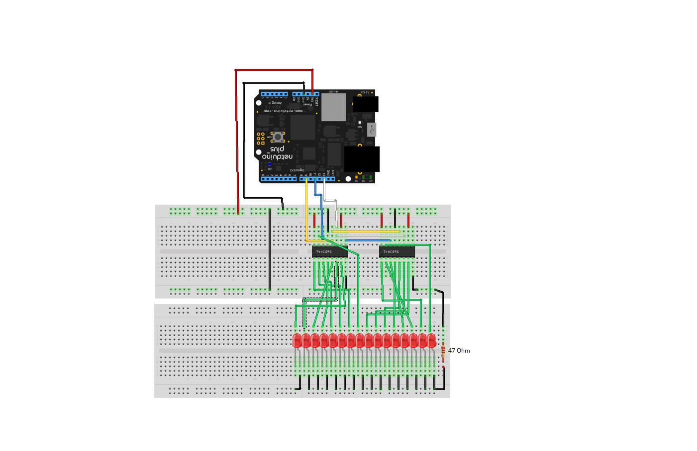
Shift Register Cascade
Looking at the diagram, the wiring seems confusing. The green wires show the wiring of the LEDs to the outputs of the shift registers. The outputs of the shift register should be wired to the LEDs from right to left in the order QA through QH. This is probably the most confusing part of the diagram due to the number of connections but these all follow the simple principle of wiring the output from the chip to the LED and then through to ground.
If we throw away the green connections then we have a few key connections:
- SI on the left most shift register (pin 14) should be connected to MOSI on the Netduino.
- SCK on the left most shift register (pin 11) should be connected to SPCK on the Netduino
- /G on the left shift register (pin 13) should be connected to the latch pin on the Netduino
- RCK on the left shift register (pin 12) should be connected to ground
When cascading the registers the following connections should be made for the registers to the right of the first register:
- Serial Out (pin 9) of the left chip to SI (pin 14) of the right chip
- SCK of both chips (pin 11) should be connected
- /G on both chips (pin 13) should be connected
The data is fed into the shift registers from the left with bit 0 appearing on the far right. The clock and the enable is fed into both chips at the same time. The serial data is fed into the chip on the far left and is cascaded on to the chip to it’s immediate right. Further chips can be added to the right and cascaded in the same manner. In this way, bit 0 will always be at the far right of the shift registers.
Software
The software used the SPI interface on the Netduino to communicate with the shift registers. An important note in the documentation is that the chip has a two stage process for transferring the data from the input to the output. Each bit is transferred into the shift register on the rising edge of the clock pulse. This is then transferred on to the output on the following rising edge. This is fine for all but the last bit as it will need a rising edge in order to be transferred to the output. Standard SPI has the idle clock set to low. As such this could lead to the final bit not being transferred to the output. In order to overcome this the SPI interface was set to the idle clock being high. The final transition from an active clock to an idle clock will then trigger the transfer of the final bit from the input to the output.
From a software engineers point of view a shift register is nothing more than an array of boolean values and this is the approach that was taken. The software holds an array of boolean values (multiples of 8 bits as the shift registers targeted are 8 bit registers). The software holds an array of values which the programmer can then choose to output to the registers.
The variable declarations become:
/// <summary>
/// Array containing the bits to be output to the shift register.
/// </summary>
private bool[] _bits;

/// <summary>
/// Number of chips required to implement this ShiftRegister.
/// </summary>
private int _numberOfChips;

/// <summary>
/// SPI interface used to communicate with the shift registers.
/// </summary>
private SPI _spi;
The constructor for the class instantiates the array holding the number of bits in the shift register and the SPI interface:
public ShiftRegister(int bits, Cpu.Pin latchPin = Cpu.Pin.GPIO_Pin8, SPI.SPI_module spiModule = SPI.SPI_module.SPI1, uint speedKHz = 10)
{
    if ((bits > 0) && ((bits % 8 ) == 0))
    {
        _bits = new bool[bits];
        _numberOfChips = bits / 8;
        for (int index = 0; index < bits; index++)
        {
            _bits[index] = false;
        }

        SPI.Configuration config;

        config = new SPI.Configuration(SPI_mod: spiModule, ChipSelect_Port: latchPin, ChipSelect_ActiveState: false, ChipSelect_SetupTime: 0, ChipSelect_HoldTime: 0,  Clock_IdleState: true, Clock_Edge: false, Clock_RateKHz: speedKHz);

        _spi = new SPI(config);
    }
    else
    {
        throw new ArgumentOutOfRangeException("ShiftRegister: Size must be greater than zero and a multiple of 8 bits");
    }
}
A little bit operator overloading on the indexer allows the programmer to address the individual bit in the shift register:
/// <summary>
/// Overload the index operator to allow the user to get/set a particular
/// bit in the shift register.
/// </summary>
/// <param name="bit">Bit number to get/set.</param>
/// <returns>Value in the specified bit.</returns>
public bool this[int bit]
{
    get
    {
        if ((bit >= 0) && (bit < _bits.Length))
        {
            return (_bits[bit]);
        }
        throw new IndexOutOfRangeException("ShiftRegister: Bit index out of range.");
    }
    set
    {
        if ((bit >= 0) && (bit < _bits.Length))
        {
            _bits[bit] = value;
        }
        else
        {
            throw new IndexOutOfRangeException("ShiftRegister: Bit index out of range.");
        }
    }
}
The final piece of the jigsaw is to allow the programmer to send the data to the shift register:
/// <summary>
/// Send the data to the SPI interface.
/// </summary>
public void LatchData()
{
    byte[] data = new byte[_numberOfChips];

    for (int chip = 0; chip < _numberOfChips; chip++)
    {
        data[chip] = 0;
        byte bitValue = 1;
        int offset = chip * 8;
        for (int bit = 0; bit < 8; bit++)
        {
            if (_bits[offset + bit])
            {
                data[chip] |= bitValue;
            }
            bitValue <<= 1;
        }
    }
    _spi.Write(data);
}
This method is really the work horse as it converts the bits into an array of bytes which are transferred to the shift registers.
Testing it Out
Testing should be easy, lets walk through all of the bits for a 16 bit register made by having two shift register connected together:
public static void Main()
{
    ShiftRegister shiftRegister = new ShiftRegister(16, Pins.GPIO_PIN_D9);
    while (true)
    {
        for (int index = 0; index < 16; index++)
        {
            shiftRegister[index] = true;
            shiftRegister.LatchData();
            Thread.Sleep(100);
            shiftRegister[index] = false;
        }
    }
}
This example uses two registers (16 bits) and uses pin D9 as the enable pin for the register. The code sets, displays and then resets each bit starting at bit 0 through to bit 15.
The full code for the shift register class can be found here (ShiftRegister.zip).