Simple LED and Transistor Switch
Sunday, January 2nd, 2011In my previous post I mentioned that I was working towards controlling a LED from the Netduino. In fact the aim is to be able to control more than an LED but this is a start. Step two is to use a transistor to control the LED by using the transistor as a switch. By doing this I hope to be able to use this knowledge to control other devices which draw more current than the Netduino can supply (i.e. motors etc.).
Objective
The aim of this experiment is to control the circuit in the simple LED experiment using a transistor as a switch. The LED should light when the input to the transistor is high and the LED should turn off when the input to the transistor is low.
The circuit should draw as little current as possible in order to switch the LED on in order that the switch can be used by the Netduino Plus.
Design
The circuit is a simple transistor circuit using the transistor as a switch. In this case the transistor is either off or fully on (The voltage across the collector and emitter is almost zero and the transistor is saturated and cannot pass any more collector current). The circuit design becomes something like this:
![]()
Note that the current limiting resistor for the LED circuit has been change to 100 ohms (as opposed to 47 ohms in the previous post).
The resistor R2 is used to drive the transistor. By breaking the connection we turn the transistor off and hence turn the LED off. By restoring the connection we turn the transistor back on and hence turn the LED on. The value of R2 has been chosen to provide a very small current to the base of the transistor.
| Current to base of the transistor | = V / R (from ohms law) |
| = 3.3V / 2200 ohms | |
| = 1.5 mA |
This falls well below the maximum current of 8 mA per pin provided by the Netduino Plus.
So we now have the limited current to trigger the switch and then only thing remaining is to work out which transistor to use. For this I used The Electronics Club pages regarding transistors. By following their calculations regarding choosing a suitable NPN transistor we get the following:
| Load current on the collector | = Supply voltage / Load resistance |
| = 19 mA (modified from the last post) |
The transistors minimum current gain (hFE) should be at least five times the current being driven through the load (Ic) divided by the maximum output from the chip driving the switch (i.e. from the Netduino Plus).
| hFE(min) | = 5 * (load current Ic / maximum current from the chip driving the circuit) |
| = 5 * (26 mA / 8 mA) | |
| = 16.25 (minimum value) |
On this basis the BC108 transistor was chosen as the hFE and the Ic values fall well within those calculated. For the BC108:
| IC | 100 mA |
| hFE | 110 |
The next step is to calculate the value for the resistor placed between the base of the transistor and the switching current.
| RB | = (Vc * hFE) / (5 * Ic) |
| = (3.3V * 100) / (5 * 19mA) | |
| = 3473 ohms |
The value for RB was set to 3k3 ohms.
Putting It All Together
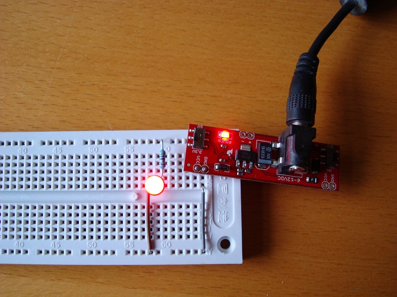
The circuit was assembled using the values in the diagram above. By connecting the base of the transistor to the 3.3V line through the 2K2 LED turned the LED on, disconnecting the resistor turned the LED off:
![]()
And so some measurements:
| Measurement | Value |
| Voltage drop across R1 | 1.34 V |
| Voltage drop across LED | 1.86 V |
| Voltage drop across R2 | 2.52 V |
| Current through R2 | 0.5 mA |
The next stage of the project is to connect this to the Netduino Plus and use this to turn the LED on / off preferably without burning it out :).