KiCAD Relative Positioning

Most of the PCBs I make have mounting holes in the final layout to allow the boards to be firmly attached to 3D printed cases or mounts. When I first started using KiCAD I found it difficult to position the arc edge cuts around the mounting holes accurately. This was not too critical but it was a little annoying. The error in positioning the arcs was minor and is difficult to see but it would be good to fix the problem.
This was something I finally worked out in the last design I sent to manufacture and thought it would be something others might want to know about.
Board Layout
Most of my designs usually result in a square or rectangular board. The boards are simple and don’t really need to fis an irregularly shaped case. So most of the time I am trying to place a hole at the corner of say a square and then place an edge cut around the hole, something like this:

PCB with two mounting holes
Placing the mounting holes is a simple case of editing the x and y positions of the mounting hole and ensuring that the holes are lined up correctly. The edge cuts are a little more difficult to position consistently when placing them by hand.
Accurate Edge Cuts
As noted above, the first stage is to place the mounting holes on a rectangular grid and using the x and y positions to place the holes. Next step is to create an arc centred on one of the mounting holes with the appropriate radius. This can be done in using the centre of the mounting holes as the starting point and then sweeping an arc through 90 degrees around the hole:

Arc and Hole
Next up we duplicate the arc, rotate it through 90 degrees and move to one of the opposite mounting holes:
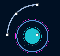
Duplicated arcs
As you can see, the duplicated arc is not centred on the opposite mounting hole. We now use the positioning tools to align the arc with the mounting hole. Start by selecting the arc and then right click to bring up the context menu and select Position Relative To… from the context menu:
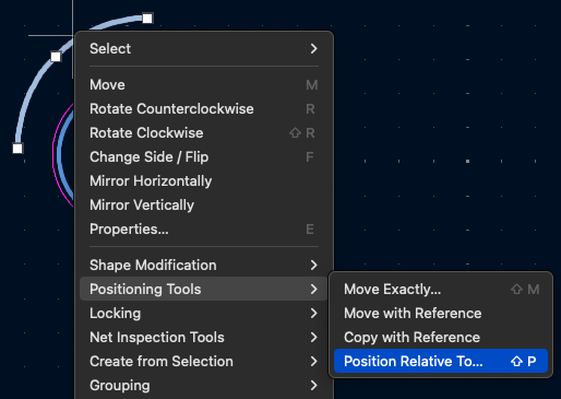
Positioning context menu
From the positioning dialog click on the Select Item button:
Select item button
Next, select the reference item, in this case it is the mounting hole:
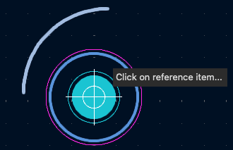
Select the reference item
The positioning dialog will now reappear with the reference item selected. Ensure that the Offset X and Offset Y are both set to 0 and click OK.
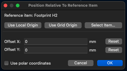
Position dialog box
The arc should now move and be centred on the mounting hole.

Final arc position
Finally, repeat for the remaining 2 mounting holes.
Conclusion
This method allows for the board outline to be defined more accurately then lining up the arcs by eye. It is simple to do and only takes a few minutes to complete. The arcs can then be used as the anchors for the linear edges of the board.
This technique is also useful for positioning other parts on any design.
Sunday, March 10th, 2024 at 4:04 pm • KiCad, Tips • RSS 2.0 feed Both comments and pings are currently closed.
