Home Computing
Saturday, May 7th, 2011These guys take home computing to a whole new level:
These guys take home computing to a whole new level:
After many a hour playing (and swearing) I think I have now managed to get the Netduino talking to a Bluetooth module in command mode. There were many teething problems along the way but I think the source code which is attached along with the notes should allow the reconfiguration/control of the Bluetooth module from the Netduino.
There were two objectives for this project, namely
This is a mainly software project as the connections are straightforward.
The Bluetooth module chosen was a Roving Networks RN-42. This device can be found on a breakout board on several hardware sites (Proto-Pic or Sparkfun) and provides a simple COM connection to the Netduino.
Wiring up the module was simple, only six connections to worry about 🙂
There were a few teething problems along the way. The major issue was that at the time I was not able to get access to the correct documentation for the module. A little persistence and I finally had it.
So the first task was to get the module talking to my PC. Powering on the module and then getting my PC to search for Bluetooth device was simple. The PC found the device and paired without much fuss. I opened PuTTY and set the COM port parameters and I was talking to the module.
This is where it started to get interesting (i.e. frustrating) as I had missed a crucial part of the documentation. In order to enter command mode you must enter the command string within 60 seconds of the module being powered up. Once I had this figured it was a doddle. PuTTY allowed me to enter commands and displayed the responses.
So at this point I knew I had a working Bluetooth module and it could connect to the the PC in both data and command mode.
The next problem was to bring the module under the control of the Netduino. This required the a few design decisions. The module can return both single and multi-line responses to commands.
The simplest problem was the single line response. The system simply looped until a line of data was returned.
For the multi-line response it was necessary to allow the system some processing time. The approach taken was to allow the user to specify a wait time. This would allow the Bluetooth module to fill the buffer with response to the command. This puts the Netduino to sleep far a while. Again, this was considered acceptable as the system would be configuring the Bluetooth module – i.e. a startup overhead rather than a run-time overhead.
The library is pretty simply to use with the constructor taking the parameters needed to create a new instance of the class and connect it to the Bluetooth module and the few remaining public methods allowing the user to talk to the module.
The public constructor takes five parameters which essentially allow the class to configure the serial port used to communicate with the module.
public RovingNetworks(string port, BaudRate baudRate, Parity parity, int dataBits, StopBits stopBits)
This method switches the module into command mode. It must be called within 60 seconds (if using default configuration) of the module being turned on.
This method returns the module to data mode.
This methods has two variants. The first is used for simple commands and returns a single string which is the one line response from the module. The second is for more verbose commands where more than one line is returned from the module.
For the majority of commands only one line of test is returned and so the simple one line method can be used. This will loop until a response has been received by the system. This response is then returned to the user.
public string SendCommand(string command)
{
    string result;

    ClearBuffer();
    _bluetoothModule.Write(Encoding.UTF8.GetBytes(command), 0, command.Length);
    result = ReadLine();
    while (result == "")
    {
        result = ReadLine();
    }
    return (result);
}
The second method assumes a multi-line response from the command. In order to collect these responses together the system pauses a while. It is important that this pause is long enough for the module to process the command and generate the response but not too long as this will block the thread for the specified timeout period.
public ArrayList SendCommand(string command, int timeout)
{
    ArrayList result;
    string line;

    ClearBuffer();
    result = new ArrayList();
    _bluetoothModule.Write(Encoding.UTF8.GetBytes(command), 0, command.Length);
    Thread.Sleep(timeout);
    line = ReadLine();
    while (line != "")
    {
        result.Add(line);
        line = ReadLine();
    }
    return (result);
}
The following small program shows the execution of a single command which returns some configuration information for the module.
RovingNetworks rn42;

rn42 = new RovingNetworks(Serial.COM1, BaudRate.Baudrate115200, Parity.None, 8, StopBits.One);
if (rn42.EnterCommandMode())
{
    Debug.Print("Success");
    ArrayList result = rn42.SendCommand("Drn", 500);
    foreach (string str in result)
    {
        Debug.Print(str);
    }
    Thread.Sleep(Timeout.Infinite);
}
else
{
    Debug.Print("Oh dear...");
}
The code is available RN 42 Bluetooth Source Code There’s not a lot of it and it’s reasonably well commented so we’ll call it a day.
Edit (25th April 2011): Implemented IDispose and updated the source code.
Looks like Microsoft have released the beta of Silverlight 5. Details of the new features can be found here.
Debugging data binding ! Finally 🙂
Today marks two of space explorations anniversarys, the 50th anniversary of the first manned space flight and the 30th anniversary of the first shuttle flight. I am too young to remember the first manned flight but I do remember the first shuttle flight and landing.
Spring is here, well it feels like it anyway. The frogs and the newts are cavorting in the wildlife pond – nature has woken from the cold clutches of winter. This can mean only one thing, I will have to return to my second job, that of mud re-locator for my wife. After six years we are starting to see the light at the end of the tunnel and I get the feeling this year may see the main jobs out of the way.
When we purchased the house the garden at the rear of the house was mostly lawn and not much else. The past few years have seen us create a wildlife area, a vegetable plot, put up a greenhouse and create an area for growing fruit. This year (and a little bit of next year) should see the last of the major reconstruction work on the leisure area. So on with the mud relocation and less of the hobby electronics and software engineering.
So first job, create a 40 metre by 10 metre lawn on uneven land (after levelling it of course).
I may be sometime…
Update 18 March 2011: This is where this series of posts finishes for the minute as I appear to have fried the MAX7219 (or something else is wrong with the setup) as I can send commands to it but the output does not make any sense. I’ll have to return to this series when I have a new chip.
This is the second in a series of posts discussing the MAX7219 LED driver chip being used to drive a four digit, seven segment LED display. The series is made up of the following posts:
The objective of this post is to start to flesh out the code (which will be presented in the final post) to start to send commands in the form of 16 bit unsigned shorts to the MAX7219.
All of the hardware remains as before and only the software changes. As before, the logic analyser is used to verify the results.
The software required a minor update to convert the output to an array of ushorts and put the register in the msb and the data in the lsb.
The main program does little more that send two commands to the logic analyser, namely a command to enter normal operation followed by a command to restrict the number of digits to four.
The results can be seen here:

This image shows the command to restrict the display to four digits being sent over the SPI bus.
The next step is to complete the wiring and to start to send display data to the MAX7219.
Update 18 March 2011: This is where this series of posts finishes for the minute as I appear to have fried the MAX7219 (or something else is wrong with the setup) as I can send commands to it but the output does not make any sense. I’ll have to return to this series when I have a new chip 🙁
This series of posts will discuss using the MAX7219 LED driver chip to drive a four digit, seven segment LED display. The series is made up of the following posts:
The following posts provide some background information as these are similar projects:
The objective of these post is to connect the Netduino Plus to the breadboard and get a 5V logic signal representing a series of bytes. In order to do this it is necessary to convert the output from the Netduino Plus from 3.3V to 5V. I propose to experiment and use a 7408 quad 2 input AND gate to convert the 3.3V signal up to 5V. So for this post we will need the following components:
Part of this exercise is to see if we can convert a 3.3V signal into a 5V signal. This is necessary as the MAX7219 uses 5V inputs. The quad input AND gate was chosen to do this for no other reason than I had a few spare in the component box. The data sheet for this chip states that the minimum voltage for a high input is 3.15V when the chip is supplied with 4.5V. A quick experiment shows that a 3.3V input signal to this chip does indeed result in a high output.
So by connecting one of the inputs to the AND gate to 5V and the second to the signal source, then the output from the gate should reflect the input but translated from 3.3V to 5V.
One point to note is that the chip will take a little while for the signal on the inputs to be reflected on the output pins. This application will be running at a low frequency (10KHz) and so the chip should be able to keep up.
The software is a simple starter program which cycles through the bytes from 0 to 255 and output’s these bytes on the SPI bus. The Saleae logic analyser is used to verify that the data is being output correctly. A small test program should demonstrate that the data is being transmitted on the bus correctly:
using System;
using System.Net;
using System.Net.Sockets;
using System.Threading;
using Microsoft.SPOT;
using Microsoft.SPOT.Hardware;
using SecretLabs.NETMF.Hardware;
using SecretLabs.NETMF.Hardware.NetduinoPlus;

namespace NetduinoPlusTestApplication
{
    public class Program
    {
        public static void Main()
        {
            SPI.Configuration config;
            SPI spi;
            byte[] b;

            config = new SPI.Configuration(Pins.GPIO_PIN_D10, false, 0, 0, false, false, 10, SPI.SPI_module.SPI1);
            spi = new SPI(config);
            b = new byte[1];

            while (true)
            {
                for (byte v = 0; v <= 255; v++)
                {
                    b[0] = v;
                    spi.Write(b);
                    Thread.Sleep(20);
                }
            }
        }
    }
}
The following table shows how the Netduino Plus is connected to the 74HCT08N
| 74HCT08N | Connection |
| 2, 5, 10, 13, 14 | +5V |
| 7 | Ground |
| 12 | Netduino Plus digital pin 10 (used for CS) |
| 1 | Netduino Plus digital pin 11 (MOSI) |
| 4 | Netduino Plus digital pin 13 (Clock) |
The ground on the Netduino Plus should also be connected to the ground on the breadboard.
After completing the wiring the logic analyser was hooked up and the following trace appeared:

Scrolling through the trace show each of the ASCII characters being interpreted correctly.
So the next step it to start to build the class which will talk to the MAX7219.
Not me, now that would take some imagination 🙂 The ZX81, probably the first cheap usable home computer.
This had me thinking about how times have moved on looking at my hobbies then and now. At the time I had an amateur interest in electonics. This lasted about 4 years and then lapsed as I could not find the money to support the hobby and go through university at the same time. 30 years on and I now find myself playing with hardware once again.
Looking back to 1981 we had the ZX81
In 2011 I find myself playing with the Netduino
Progress 🙂
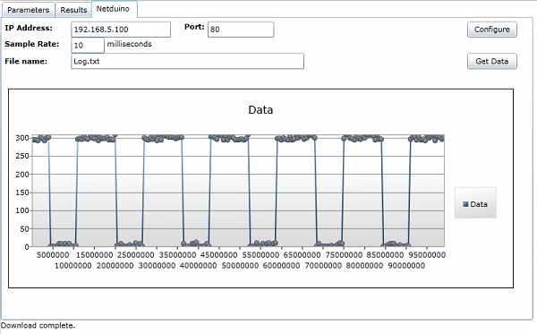
A while ago I wrote about my renewed relationship with the NE555 when I produced a simple astable circuit. The experience of trying to work out the values lead me to think about writing a calculator application. This lead me to wonder how I could validate the results given that I do not have an oscilloscope – simple add a data logger to the Netduino and use that. The following shows how I did it and provides some information about how the code works.
Write application which provides the functionality:
This will require two applications, one to interact with the user and perform the calculations and data plotting and one application to capture the data on the Netduino.
This application is an extension to the Silverlight application which I documented here. This has the core functionality required to allow the Netduino Plus to communicate with a Silverlight application. A few slight changes were required, namely:
For the first of the changes we simply need to add some additional variables to store the configuration and modify the ProcessCommand method. The system uses the Command.html special file (as before) to receive commands/requests from the user. The valid actions implemented are as follows:
| Action | Parameters | Description |
| t | Test the connection. This simply returns a Hello string to the calling application. | |
| g | Get the preconfigured file and send this back to the caller. | |
| c | SampleRate and FileName | Configure the Netduino data logger. The system will configure the Netduino to log data every SampleRate milliseconds and store the results in the specified file. |
The last part of the change to the web server is to provide a mechanism to communicate the change to the data logging component. This done using an event as the data logger and the web server are executing in different threads.
The next change required is to implement the data logging functionality. The data logging runs in the main thread. The on board switch was used to trigger data collection rather than having the Netduino log data permanently. The on board LED was also used to indicate if the board is collecting data. A Timer was used to trigger the collection of data from the analog pin. This meant that the board can capture at most 1000 samples per second.
private static void onBoardButton_OnInterrupt(uint data1, uint data2, DateTime time)
{
    if (data2 == 0)
    {
        if (_logging)
        {
            _timer = null;
            _onBoardLED.Write(false);
            _logging = false;
        }
        else
        {
            using (TextWriter tw = new StreamWriter(@"SD" + _fileName, false))
            {
                tw.WriteLine("Ticks,Data");
                tw.Close();
            }
            _startTime = Utility.GetMachineTime().Ticks;
            _timer = new Timer(new TimerCallback(CollectData), null, 0, _sampleRate);
            _onBoardLED.Write(true);
            _logging = true;
        }
    }
}
This code is tied to the on board switches interrupt. It starts and stops the logging depending upon the current state. A logging start request opens the specified file and puts the header into the file. This effectively deletes and results already stored in the file. The timer is created and tied to the CollectData callback. This callback simply reads the pin and writes the number of ticks since the start of the logging session along with the reading from the pin.
private static void CollectData(object o)
{
    string data;

    data = Utility.GetMachineTime().Ticks - _startTime + "," + _analogInput.Read();
    using (TextWriter tw = new StreamWriter(@"SD" + _fileName, true))
    {
        tw.WriteLine(data);
        tw.Close();
    }
}
This is where the project began to take on a life of it’s own. The code discussed here consumed the majority of the time spent on the project. The code is fairly well commented and so the main features will be discussed here.
The project uses MVVM to implement a calculator for the NE555. This results in little code in the code behind for the main page. What code there is simply creates a new instance of the View Model class and calls methods in the class when buttons on the interface are clicked. The remaining communication is achieved using data binding in Silverlight.
The calculator can be used to calculate one of the following (given the remaining three values):
The system takes three of the specified values and calculates the remaining. The values for the components can come from three sources, a standard component, a user specified value or a range of values.
If single component values are used (either standard components or user values) then a single result set is generated. If a range of values are selected for one or more of the components then the system will generate a table of values with one line for each of the requested values.
So much for discussing the application, it is probably just as easy to try the application which can be found here.
The first tab (Parameters on the application collects the parameters for the calculations and allows the user to request that the results are calculated.
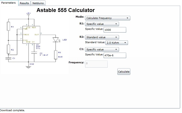
NE555 Calculator
The next tab (Results) presents the results of the calculation.

The final tab (Netduino) allows the application to communicate with a Netduino Plus.
Although the Silverlight application is hosted on my web site, you can still use this to communicate with your Netduino Plus if it is connected to your network.
The resulting application is more or less complete. There are a few things which could be done to make it more robust or more useful, namely:
These are left as an exercise for the reader.
The source files for this project can be found here:
Astable NE555 Silverlight Calculator
As usual, these sources are provided as is and without warranty. They are used at your own risk.
The Silverlight application can be run from a web site or from Visual Studio. The web server needs a little more than just running the project on the Netduino. You will also have to place the clientaccess.xml policy file on the SD card as Silverlight requests this file in order to determine if it allowed to talk to the web server.
I’ve been considering getting one of these for a while and it finally arrived today. First impressions, well packed sturdy and smaller than I thought it would be. The software installed without a hitch. Powered up and connected to the Netduino to check it works.
A little test program:
OutputPort output = new OutputPort(Pins.GPIO_PIN_D0, false);
SerialPort com2 = new SerialPort(SerialPorts.COM2, 9600, Parity.None, 8, StopBits.One);

com2.Open();
while (true)
{
    output.Write(true);
    Thread.Sleep(10);
    output.Write(false);
    Thread.Sleep(10);
    com2.Write(Encoding.UTF8.GetBytes("Hello, world"), 0, 12);
}
It took longer to write the test program than to install the software and hook up the analyser.
And some results:

Well, the first program everyone writes has to say “Hello, world” – well it does if you are an old C programmer anyway.

