In the words of Connor MacLeod from Highlander
There can be only one.
Every value in a Rust application has one owner and only one owner. When the owner of an value goes out of scope then the value is disposed of and is no longer valid.
The Rust Programming Language (Chapters 4 and 5)
These chapters cover the following topics:
- Ownership
- References and Borrowing
- Slices
- Structs and Methods
Ownership, references and borrowing determine how an object can be accessed and potentially modified. The strict rules are designed to reduce the possibility of common C/C++ issues such as use after free and general pointer access violations.
Structs and methods are the start of the journey into object orientated programming.
Scopes
Scoping rules pretty much follow the same rules as C/C++ and as such are familiar. Any pair of braces open and close a new scope. So a function introduces a new scope. A new scope can also be created with a pair of braces inside an existing scope.
Ownership, References and Borrowing
As Connor MacLeod said, “There can be only one” and in this case, there can be only one owner of a value.
Calling a function can change the ownership of a variable depending upon the type of the variable. Some types implement the copy trait which makes a copy of the variable on the stack. Types that do not implement the copy trait will have their ownership transferred to the function. The transfer of ownership means that the original variable is no longer valid when the function returns.
Consider the following code:
fn print_integer(x: i32) {
    println!("Integer value: {}", x);
}

fn print_string(s: String) {
    println!("String value: {}", s);
}

fn main() {
    let x: i32 = 42;
    println!("Original integer: {}", x);
    print_integer(x);
    println!("Original integer after function call: {}", x); // This line works fine since integers implement the Copy trait.

    let s: String = String::from("Hello, world!");
    println!("Original string: {}", s);
    print_string(s);
    println!("Original string after function call: {}", s); // This line will cause a compile-time error due to ownership rules.
}
Compiling the above code generates the following error output:
error[E0382]: borrow of moved value: `s`
  --> src/main.rs:24:57
   |
21 |     let s = String::from("Hello, world!");
   |         - move occurs because `s` has type `String`, which does not implement the `Copy` trait
22 |     println!("Original string: {}", s);
23 |     print_string(s);
   |                  - value moved here
24 |     println!("Original string after function call: {}", s); // This line will cause a compile-time error due to owne...
   |                                                         ^ value borrowed here after move
   |
note: consider changing this parameter type in function `print_string` to borrow instead if owning the value isn't necessary
  --> src/main.rs:16:20
   |
16 | fn print_string(s: String) {
   |    ------------    ^^^^^^ this parameter takes ownership of the value
   |    |
   |    in this function
   = note: this error originates in the macro `$crate::format_args_nl` which comes from the expansion of the macro `println` (in Nightly builds, run with -Z macro-backtrace for more info)
help: consider cloning the value if the performance cost is acceptable
   |
23 |     print_string(s.clone());
   |                   ++++++++

For more information about this error, try `rustc --explain E0382`.
error: could not compile `hello_world` (bin "hello_world") due to 1 previous error
An awful lot of output to digest.
Calls to print_integer work because the i32 type is simple and this implements the copy trait. This means a copy of the value in x is made on the stack. The function print_integer therefore operates on the copied value and not the variable x defined in main.
print_string works differently as it is operating on a complex value that does not implement the copy trait. Complex values are usually allocated on the heap. Calling print_string moves the ownership of s to the print_string function and the object is dropped at the end of the function making future uses of s in main invalid.
References
The compiler suggested one option for the problem in the above code, to clone the string and pass this to the print_string function. Another solution is to use references. Here the application allows the use of the object without transferring ownership. In this case the object passed is not dropped at the end of the function.
This is known as borrowing.
The above code can be modified to use references:
fn print_string(s: &String) {
    println!("String value: {}", s);
}

fn main() {
    let s: String = String::from("Hello, world!");
    println!("Original string: {}", s);
    print_string(&s);
    println!("Original string after function call: {}", s); // This line will cause a compile-time error due to ownership rules.
}
Running this code with cargo run generates the following output:
Original string: Hello, world!
String value: Hello, world!
Original string after function call: Hello, world!
No more compiler errors.
Function parameters can also be declared as mutable meaning that the original variable can be modified by the function. Modifying the above code to the following:
fn print_string(s: &mut String) {
    println!("String value: {}", s);
    s.push_str(", world!");
}

fn main() {
    let mut s = String::from("Hello");
    println!("Original string: {}", s);
    print_string(&mut s);
    println!("Original string after function call: {}", s);
 }
Running the application results in the following output:
Original string: Hello
String value: Hello
Original string after function call: Hello, world!
print_string is now able to borrow the parameter and modify the value.
I suspect that a lot of time (initially) will be spent fighting the borrow checker.
Structs and Methods
Structs provide the ability to collect together related data items and are similar to structs in C/C++. Methods are functions related to a struct giving us the basics of object orientated programming. The methods are implemented against a type:
struct Rectangle {
    width: u32,
    height: u32,
}

impl Rectangle {
    fn area(&self) -> u32 {
        self.width * self.height
    }
}
In the above code, the area method is implemented against the Rectangle structure.
Language Highlights
One stand out feature with structs is the ability to easily copy unchanged fields from one structure to a new version of the same type of structure. This is best illustrated with an example.
#[derive(Debug)]
struct Person {
name: String,
house_number: u16,
street: String, // Rest of address fields omitted for brevity.
mobile_number: String
}
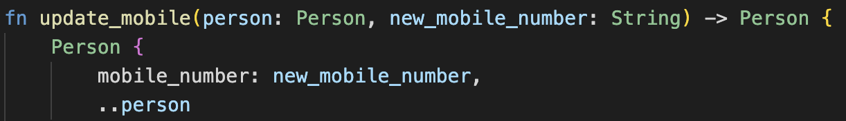
fn update_mobile(person: Person, new_mobile_number: String) -> Person {
Person {
mobile_number: new_mobile_number,
..person
}
}
fn main() {
let person = Person {
name: String::from("Fred Smith"),
house_number: 87,
street: String::from("Main Street"),
mobile_number: String::from("+44 7777 777777")
};
println!("Before update: {:?}", person);
let updated_person = update_mobile(person, String::from("+44 8888 888888"));
println!("After update: {:?}", updated_person);
}
Running this application with cargo run generates the following output:
Before update: Person { name: "Fred Smith", house_number: 87, street: "Main Street", mobile_number: "+44 7777 777777" }
After update: Person { name: "Fred Smith", house_number: 87, street: "Main Street", mobile_number: "+44 8888 888888" }
A contrived example maybe but it illustrates the use of ..person to copy the unchanged fields into the new new Person structure.
Another nice feature is the field initialisation for structure members. If a field has the same name as the value being used to initialise it then we can omit the field name. For instance we could modify the update_mobile function above to the following:
fn update_mobile(person: Person, mobile_number: String) -> Person {
    Person {
        mobile_number,
        ..person
    }
}
Note the change to the parameter name to mobile_number to match the field name in the Person struct.
Conclusion
The borrow checker is going to be frustrating for a while with the benefit that if the code compiles it is highly likely to be bug free. The borrow checker also aid in the safety of multithreaded applications.
New Links
Came across a new tool for code linting: Clippy.
Consider the following function:
fn print_integer_and_increment(x: &mut i32) {
    println!("Integer value: {}", x);
    *x = *x + 1;
}
This code compiles without error and works as expected. Running the command cargo clippy to lint the code results in the following output:
warning: manual implementation of an assign operation
  --> src/main.rs:18:5
   |
18 |     *x = *x + 1;
   |     ^^^^^^^^^^^ help: replace it with: `*x += 1`
   |
   = help: for further information visit https://rust-lang.github.io/rust-clippy/master/index.html#assign_op_pattern
   = note: `#[warn(clippy::assign_op_pattern)]` on by default

warning: `hello_world` (bin "hello_world") generated 1 warning (run `cargo clippy --fix --bin "hello_world"` to apply 1 suggestion)
    Finished `dev` profile [unoptimized + debuginfo] target(s) in 0.11s
Running the command cargo clippy –fix –bin “hello_world” –allow-dirty makes the suggested change automatically.
Next Up
Enums, Pattern Matching, Modules and Project structure.