In a previous post I mentioned that replacing a single LED in the centre of a matric would be murder and so it will be. The matrix I have in mind is an 8 x 8 x 8 LED cube controlled by a Netduino board. Now it should be obvious that there are not enough pins to connect 512 LEDs to the Netduino without some magic being involved. This is where the Persistence of Vision post comes into the picture. In theory, it should be possible to control an array using a group of shift registers and a multiplexer circuit. So for the next few weeks this is what I’ll be looking at.
Multi-Threading
The previous post on Persistence of Vision had a simple while loop which allowed 16 LEDs to be controlled from the main program loop. In the final program this will be too cumbersome and timing is almost certainly to become an issue. To overcome this we will need to have the display logic separated from the control logic. This will allow the display to be continuously updated whilst the main program loop is working out what should be displayed next. The following tests this concept by turning on on LED at a time in a bank of 8. If this project has a chance of working then the 8 LEDs should all appear to be switched on permanently.
Hardware
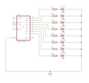
The hardware is relatively simple. We have one shift register connected to the Netduino. This is in turn connected to 8 LEDs through current limiting resistors. The schematic looks something like this:

Software
The software requires us to take the display logic from previous posts and add this to a new class. This class will need to have a method executing in it’s own thread in order to allow the main program and the display driver to run at the same time. So splitting the display code into it’s own class we get something like this:
class LEDCube
{
    /// <summary>
    /// SPI bus to use to send data to the shift registers.
    /// </summary>
    SPI spi = null;

    /// <summary>
    /// CSPI bus configuration
    /// </summary>
    SPI.Configuration config;

    /// <summary>
    /// Buffer holding the display data.
    /// </summary>
    private byte[] buffer;

    /// <summary>
    /// Constructor for the LEDCube class.
    /// </summary>
    public LEDCube()
    {
        config = new SPI.Configuration(SPI_mod: SPI.SPI_module.SPI1,
                                       ChipSelect_Port: Pins.GPIO_PIN_D9,
                                       ChipSelect_ActiveState: false,
                                       ChipSelect_SetupTime: 0,
                                       ChipSelect_HoldTime: 0,
                                       Clock_IdleState: true,
                                       Clock_Edge: true,
                                       Clock_RateKHz: 400);

        spi = new SPI(config);
        buffer = new byte[1];
        buffer[0] = 0;
    }

    /// <summary>
    /// Main loop which continuously updates the display from the buffer.
    /// </summary>
    public void DisplayBuffer()
    {
        while (true)
        {
            lock (buffer)
            {
                spi.Write(buffer);
            }
        }
    }

    /// <summary>
    /// Change the byte in the display buffer.
    /// </summary>
    /// <param name="b">Byte to put into the buffer.</param>
    public void UpdateBuffer(byte b)
    {
        lock (buffer)
        {
            buffer[0] = b;
        }
    }
}
Much of the code should be familiar, we have the SPI bus and config variables along with a constructor to make a new instance of the SPI bus. The new code is really the DisplayBuffer and the UpdateBuffer methods.
- DisplayBuffer is the method which has replaced the part of the main program loop which outputs the data to the SPI bus. This method is run in it’s own thread.
- UpdateBuffer simply copies new data from the caller into the display buffer.
Note that both of these methods use locking to ensure that the methods are thread safe.
The main program loop now looks something like this:
LEDCube cube = new LEDCube();
Thread display = new Thread(new ThreadStart(cube.DisplayBuffer));
display.Start();
while (true)
{
    byte value = 1;
    for (int index = 0; index < 8; index++)
    {
        cube.UpdateBuffer(value);
        value <<= 1;
    }
}
A new LEDCube is created and at first this is not running in it’s own thread. The next two lines create and start a new thread. The thread is executing the DisplayBuffer method. We then start the main program lopp which simply sets each bit in a byte and the updates the buffer in the cube using UpdateBuffer.
Next step, build the control logic for 512 LEDs.


