STM8S Independent Watchdog
Saturday, June 21st, 2014The Independent Watchdog (IWDG) allows the developer to detect software failures and reset the STM8S microcontroller restarting the application. This post demonstrates how this feature works and how the developer can change the time window for the watchdog.
Watchdogs offer the application developer a simple to use method of determining if an application has entered a state which means that it is locked or taking too long to perform an operation.
The first task is to define what we mean by too long. This will vary from one application to another but the key point is that this should be longer than the longest operation the application will perform plus a margin. Once we have this time period defined we know that the application must reset the IWDG before the time period has elapsed.
Hardware
Independent Watchdog Key Register – IWDG_KR
The Key Register controls the operation of the IWDG. The allowed values are as follows:
| Value | Description |
| 0x55 | Enable writing to the IWDG_PR and IWDG_RLR registers. These registers are write protected by default. |
| 0xAA | Reset the IWDG counter to the reload value. This value must be written to the key register periodically in order to prevent the watchdog from resetting the microcontroller. |
| 0xCC | Enable and start the IWDG. |
| 0x00 | Disable writing to the IWDG_PR and IWDG_RLR registers. |
The final value in the table is not present in revision 9 of RM0016 – Reference Manual but does appear in the header files for the STD Peripheral Library.
In researching this post a key point in the documentation was missed, namely IWDG_PR and IWDG_RLR can only be written when the IWDG has actually been enabled. This means that the IWDG needs to be running before the prescaler and reload registers can be loaded with the values required by the application. If the IWDG is not running then the system will resort to the default reset values for these registers. This gives a watchdog window of 16ms. It also means that the application has 16ms to set the desired time window through the IWDG_PR and IWDG_RLR registers before the microcontroller is reset.
Independent Watchdog Prescaler – IWDG_PR and Independent Watchdog Reload Register – IWDG_RLR
These two registers define the watchdog window and can. The default values are IWDG_PR = 0 and IWDG_RLR = 0xff. This gives a watchdog window of approximately 16ms. To change the size of the watchdog window use the table below to determine the values which are appropriate for your application:
| Prescaler Divider | Prescaler Value (IWDG_PR) | Period when RL = 0 | Period when RL = 0xff |
| 4 | 0 | 62.5 us | 15.90 ms |
| 8 | 1 | 125 us | 31.90 ms |
| 16 | 2 | 250 us | 63.70 ms |
| 32 | 3 | 500 us | 127 ms |
| 64 | 4 | 1.00 ms | 255 ms |
| 128 | 5 | 2.00 ms | 510 ms |
| 256 | 6 | 4.00 ms | 1.02 s |
The programming reference for the STM8S gives the following formula for determining the exact reset period:
T = 2 x TLSI x P x R
where:
| T | Timeout period |
| TLSI | 1 / fLSI |
| P | 2(IWDG_PR + 2) |
| R | IWDG_RLR + 1 |
Additionally, the time between the last reset of the key register (i.e. writing 0xAA to IWDG_KR) is T + 6 x TLSI.
Software
So lets look at how we can implement this:
//
//  This program demonstrates how to use the Independent Watchdog timer
//  on the STM8S microcontroller in order to detect software failures and
//  reset the microcontroller.
//
//  This software is provided under the CC BY-SA 3.0 licence.  A
//  copy of this licence can be found at:
//
//  http://creativecommons.org/licenses/by-sa/3.0/legalcode
//
#include <iostm8S105c6.h>
#include <intrinsics.h>

//--------------------------------------------------------------------------------
//
//  Setup the system clock to run at 16MHz using the internal oscillator.
//
void InitialiseSystemClock()
{
    CLK_ICKR = 0;                       //  Reset the Internal Clock Register.
    CLK_ICKR_HSIEN = 1;                 //  Enable the HSI.
    CLK_ECKR = 0;                       //  Disable the external clock.
    while (CLK_ICKR_HSIRDY == 0);       //  Wait for the HSI to be ready for use.
    CLK_CKDIVR = 0;                     //  Ensure the clocks are running at full speed.
    CLK_PCKENR1 = 0xff;                 //  Enable all peripheral clocks.
    CLK_PCKENR2 = 0xff;                 //  Ditto.
    CLK_CCOR = 0;                       //  Turn off CCO.
    CLK_HSITRIMR = 0;                   //  Turn off any HSIU trimming.
    CLK_SWIMCCR = 0;                    //  Set SWIM to run at clock / 2.
    CLK_SWR = 0xe1;                     //  Use HSI as the clock source.
    CLK_SWCR = 0;                       //  Reset the clock switch control register.
    CLK_SWCR_SWEN = 1;                  //  Enable switching.
    while (CLK_SWCR_SWBSY != 0);        //  Pause while the clock switch is busy.
}

//--------------------------------------------------------------------------------
//
//  Initialise the ports.
//
//  Configure all of Port D for output.
//
void InitialisePorts()
{
    PD_ODR = 0;             //  All pins are turned off.
    PD_DDR = 0xff;          //  All pins are outputs.
    PD_CR1 = 0xff;          //  Push-Pull outputs.
    PD_CR2 = 0xff;          //  Output speeds up to 10 MHz.
}
The code above should be pretty familiar to anyone who has been following The Way of the Register series of posts. This sets up the system clock to run at 16MHz and sets port D as an output port.
//--------------------------------------------------------------------------------
//
//  Initialise the Independent Watchdog (IWDG)
//
void InitialiseIWDG()
{
    IWDG_KR = 0xcc;         //  Start the independent watchdog.
    IWDG_KR = 0x55;         //  Allow the IWDG registers to be programmed.
    IWDG_PR = 0x02;         //  Prescaler is 2 => each count is 250uS
    IWDG_RLR = 0x04;        //  Reload counter.
    IWDG_KR = 0xaa;         //  Reset the counter.
}
We follow this up by setting up the IWDG. The prescaler and counter values should give a 1ms window.
//--------------------------------------------------------------------------------
//
//  Main program loop.
//
int main()
{
    //
    //  Initialise the system.
    //
    __disable_interrupt();
    InitialiseSystemClock();
    InitialisePorts();
    InitialiseIWDG();
    __enable_interrupt();
    __halt();
}
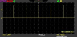
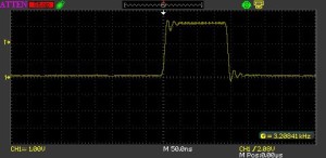
The main program configures the system and then halts the microcontroller. Without the watchdog this would the end of the application. With the watchdog we should see the microcontroller continuously resetting. This can be verified by connecting an oscilloscope to Port D. If we do this we see the output on the port rise as the microcontroller is reset and the InitialisePorts method is called.
Now replace the __halt(); statement with the following code:
while (1)
{
    IWDG_KR = 0xaa;
}
This code continuously writes the I am alive message to the IWDG key register. Doing this forces the IWDG to reset the counters with the reload values and start again. Running this application we see a flat line following the initial reset of the microcontroller. The flat line indicates that the microcontroller is not being reset.
Conclusion
The Independent Watchdog provides a simple method for detecting software failures merely writing a reset value into the key register.
Earlier the point was made that it appears that the IWDG must be enabled (and hence running) before the prescaler and reload registers can be modified. This point is critical as the microcontroller will resort to the reset values otherwise.
Although not demonstrated here it is possible for the application to determine if the application has been started through the application of power to the microcontroller or because of a reset by the IWDG. This can be determined by checking the value in RST_SR_IWDGF. This will be set to 1 if the IWDG has caused the microcontroller to be reset or 0 otherwise. This is left as an exercise for the reader.
Download
The source code for this post is available for download.


