Nikon D70 remote Control PCB Assembly
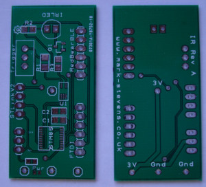
A few days ago the bare PCBs arrived from China:
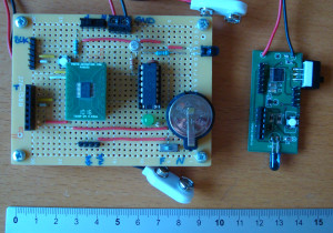
Work commitments meant that assembly has had to wait a while. I finally managed to get to put the boards together today. There is certainly a difference in size between the proto-board and the final (well nearly) PCB.
I’ve documented the assembly process of SMD boards in the past so in this post I’ll just be documenting the lessons learned from this assembly
Measure Twice, Cut Once
A carpenter friend of mine passed on this advice and it certainly rings true on this build. If you look at the back of the board there are a couple of options for connecting power to the board. The intention was to allow the board to be powered by 2 x AA batteries or a CR2032 coin cell. The connection points were supposed to be placed to allow the use of two battery holders I had purchased from Bitsbox. The measurements are a classic "off by one" case. The connections are both 2.54mm off.
Next time I’ll be double checking the footprint of the components.
Solder Paste is Opaque
I originally tried to apply solder paste to the pads for the STM8S and then position the chip on the pads. The theory is great but in practice the positioning is difficult as you cannot see the pads through the paste. Instead I found it easier to apply flux and then tack down one pin on he STM8S. This allowed the positioning of the pads and legs of the STM8S to be checked. Once I was happy with the alignment of the two I applied solder paste to the top of the legs on the chip and then heated the pins.
0402 Components are Small
A few of the components are small, very small. Most of these do not require any orientation but the LED indicating that the power is applied is small and does require a particular orientation. I found a cheap USB microscope useful to help ensure the orientation was correct.
Conclusion
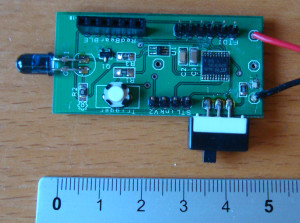
I always forget how small some of these components are but with a little practice you can work with surface mount components. The current board looks like this:
The Nikon D70 infra-red remote control prototype still triggers the camera using the trigger button. The next stage is to work on the software allowing the trigger of the remote control using the UART either by the FTDI and the RedBearBLE mini.
Tags: Electronics, LED, Software Development, STM8
Sunday, November 10th, 2013 at 4:51 pm • Electronics, STM8 • RSS 2.0 feed Both comments and pings are currently closed.


