Nikon D70 Infra-red Control
A few weeks ago I started to investigate infra-red transmitters with the intention of looking at implementing a remote control for my DSLR. The first post established the fundamentals by creating a low power transmitter and a receiver. This post takes this one step further and attempts to trigger the Nikon D70 DSLR under the control of a microcontroller.
Background
The Nikon D70 uses the ML-L3 infra-red remote control to trigger the camera. I chose this experiment as a first step to a more advanced remote control for my camera. The experiment builds upon the previous work with the STM8S and infra-red signals to trigger the DSLR.
The remote sequence required to trigger the Nikon D70 has been investigated before. I found the post by Michelle Bighignoli to be the most helpful for this particular exercise.
According to Michelle’s web site, the sequence of pulses required to trigger the camera is as follows:
- High pulse for 2000uS
- Low for 27830uS
- High for 400uS
- Low for 1580us
- High for 400uS
- Low for 3580uS
- High for 400uS
The pulse is also modulated at a frequency of 38.4KHz.
Hardware
The hardware setup is going to be relatively simple. A basic STM8S circuit is connected to the IR Transmitter circuit using port D3 on the STM8S:
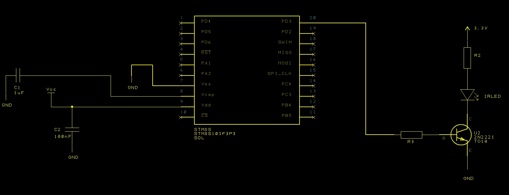
Nikon Infra-red Control Circuit
You can find out more information about both of these circuits by having a look at the following posts:
- Infra-red Transmitter and Receiver
- The Hardware section of the post Converting The Way of the Register Examples
All that needs to be done is to put this together on breadboard and setup the STM8S ready for programming.
Software
The initial version of the software will simply emit the infra-red pulse sequence as soon as it powers up as I am only looking at a proof of concept at this stage. We will not consider the topic of modulation at this stage.
Looking at the pulse sequence, the application will need to be able to generate infra-red pulses with control down to the micro-second level. The pulse widths are reasonably large, the smallest is 400uS. Taking this into consideration, the default clock speed of 2MHz will be used for the initial version of the application.
The most obvious way of controlling the pulse widths is to use one of the built in system timers. The most obvious choice is to use Timer 2 as we are going to be using the default clock speed and only require an accuracy of a micro-second or so. This will give a count in the range 0-65535 implying that the maximum pulse width will be 65,535uS assuming we use a prescalar of 2 to divide down the clock frequency used by Timer 2 to 1MHz.
The timers use two eight bit values to control the counting. This will require that the 16-bit values we have for the pulse durations will need to be broken down into two parts either before the sequence starts or as the sequence is being generated (i.e. in the timer Interrupt Service Routine (ISR)). The method chosen here is to perform this operation before the first pulse is generated. This will allow for a quicker ISR.
Design decisions over, let’s start to look at the code.
Pulse and Timer Data
The data for the timers will be broken down into the high and low byte values for the pulse duration. Along with this we will need to store the pulse type, namely high or low.
The pulse data is stored as a sequence of on/off values along with a duration in microseconds:
unsigned int pulseLength[] = { 2000U, 27830U, 400U, 1580U, 400U, 3580U, 400U };
unsigned char onOrOff[] =    {   1,      0,     1,     0,    1,     0,    1 };
//
//  Data ready for the pulse timer ISR's to use.
//
unsigned char *_counterHighBytes = NULL;
unsigned char *_counterLowBytes = NULL;
unsigned char *_outputValue = NULL;
int _numberOfPulses = 0;
int _currentPulse = 0;
And to encode the data we need a small helper method:
//--------------------------------------------------------------------------------
//
//  Prepare the data for the timer ISRs.
//
void PrepareCounterData(unsigned int *pulseDuration, unsigned char *pulseValue, unsigned int numberOfPulses)
{
    _numberOfPulses = numberOfPulses;
    if (_counterHighBytes != NULL)
    {
        free(_counterHighBytes);
        free(_counterLowBytes);
        free(_outputValue);
    }
    _counterHighBytes = (unsigned char *) malloc(numberOfPulses);
    _counterLowBytes = (unsigned char *) malloc(numberOfPulses);
    _outputValue = (unsigned char *) malloc(numberOfPulses);
    for (int index = 0; index < numberOfPulses; index++)
    {
        _counterLowBytes[index] = (unsigned char) (pulseDuration[index] & 0xff);
        _counterHighBytes[index] = (unsigned char) (((pulseDuration[index] & 0xff00) >> 8) & 0xff);
        _outputValue[index] = pulseValue[index];
    }
    _currentPulse = 0;
}
Now we have a method of converting the pulses into a format ready for the Timer and the ISR we need to setup the Timer and implement the ISR.
Timer Setup and ISR
Setup is simple as we just need to load the timer values for the first pulse, load the prescalar and enable the interrupts:
//--------------------------------------------------------------------------------
//
//  Setup Timer 2 ready to process the pulse data.
//
void SetupTimer2()
{
    TIM2_ARRH = _counterHighBytes[0];
    TIM2_ARRL = _counterLowBytes[0];
    TIM2_PSCR = _prescalar;
    TIM2_IER_UIE = 1;       //  Enable the update interrupts.
}
The ISR is relatively simple, we need to work out if there is any more pulse data to process. If there is then we load the new data into the counter, set the pulse output and exit the ISR. If there is no more data then we simply set the pulse output and disable the timer.
//--------------------------------------------------------------------------------
//
//  Timer 2 Overflow handler.
//
#pragma vector = TIM2_OVR_UIF_vector
__interrupt void TIM2_UPD_OVF_IRQHandler(void)
{
    _currentPulse++;
    if (_currentPulse == _numberOfPulses)
    {
        //
        //  We have processed the pulse data so stop now.
        //
        PD_ODR_ODR3 = 0;
        TIM2_CR1_CEN = 0;
    }
    else
    {
        TIM2_ARRH = _counterHighBytes[_currentPulse];
        TIM2_ARRL = _counterLowBytes[_currentPulse];
        PD_ODR_ODR3 = _outputValue[_currentPulse];
        TIM2_CR1_URS = 1;
        TIM2_EGR_UG = 1;
    }
    TIM2_SR1_UIF = 0;               //  Reset the interrupt otherwise it will fire again straight away.
}
Output Port
As noted, the application is using Port D3 to output the signal. A small method is required to setup the port accordingly:
//--------------------------------------------------------------------------------
//
//  Now set up the output ports.
//
//  PD3 - IR Pulse signal.
//
void SetupOutputPorts()
{
    PD_ODR = 0;             //  All pins are turned off.
    //
    //  PD4 is the output for the IR control.
    //
    PD_DDR_DDR3 = 1;
    PD_CR1_C13 = 1;
    PD_CR2_C23 = 1;
}
Main program Loop
The main program loop merely sets the stage by initialising the data, output port and timer before wiating for wny interrupts:
//--------------------------------------------------------------------------------
//
//  Main program loop.
//
void main()
{
    unsigned int pulseLength[] = { 2000U, 27830U, 400U, 1580U, 400U, 3580U, 400U };
    unsigned char onOrOff[] =    {   1,      0,     1,     0,    1,     0,    1 };
    PrepareCounterData(pulseLength, onOrOff, 7);
    __disable_interrupt();
    SetupTimer2();
    SetupOutputPorts();
    __enable_interrupt();
    PD_ODR_ODR3 = _outputValue[0];
    //
    //  Now we have everything ready we need to force the Timer 2 counters to
    //  reload and enable Timer 2.
    //
    TIM2_CR1_URS = 1;
    TIM2_EGR_UG = 1;
    TIM2_CR1_CEN = 1;
    while (1)
    {
        __wait_for_interrupt();
    }
}
Conclusion
Putting this all together and wiring up the oscilloscope we find the following generated when the circuit is turned on:

Output From Nikon Infra-red Control Circuit
Examination of the timings of the pulses reveals that the pulse widths match those in the original specification above. The small spike at the start of the pulse sequence only appears when the circuit is first turned on.
At the moment we are only generating the raw pulses, we have not started to modulate the signal using the 38.4KHz carrier. This is left for a future experiment or indeed as a exercise for the reader.
One thing I could not resist was trying this with the Nikon camera, even though the specification stated that a 38.4KHz carrier was required. Running the code with the camera set to manual mode resulted in the camera being triggered.
So some future work:
- Add the modulation
- Increase the power of the infra-red output
Tags: Electronics, STM8
Saturday, September 7th, 2013 at 7:40 am • Electronics, STM8 • RSS 2.0 feed Both comments and pings are currently closed.
