Infra-red Transmitter and Receiver
In this post we will use Mr Maxwell’s new fangled electrons to generate invisible light and transmit a signal through the luminiferous aether.
Or to put it another way, I’m learning how to use IR remote controls in microcontroller circuits. The problem with using infra-red LEDs is that you cannot really see if they are on or off. You can see if a signal is applied to the LED but this does not mean it’s generating an infra-red signal. Let’s admit it, we’ve all burnt out an LED or two in our time. So in this post I’m going to put together a couple of circuits to generate and detect infra-red signals.
Detecting IR Signals
For this circuit I am going to be using the L-7113P3C phototransistor. This component looks like an LED but is in fact a transistor:
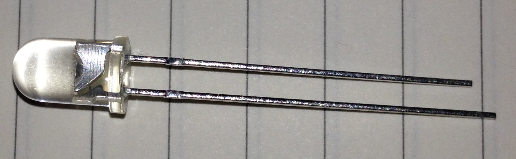
Photo Transistor
The phototransistor has two conventional connections which allow the collector and emitter to be connected to the electrical circuit but the third connector (the base) has been made sensitive to infra-red light and then exposed via a lens. The transistor becomes conductive when infra-red light hits the photosensitive base of the transistor.
The schematic for the basic detector circuit is as follows:
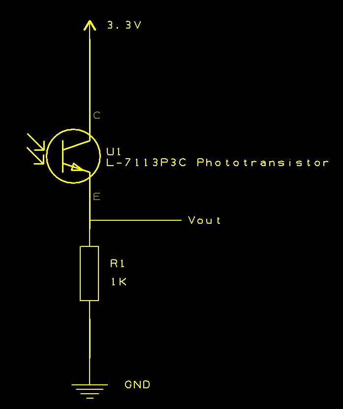
IR Receiver Schematic
Should be simple enough. Out comes the breadboard, oscilloscope and a couple of remote controls I have to hand.
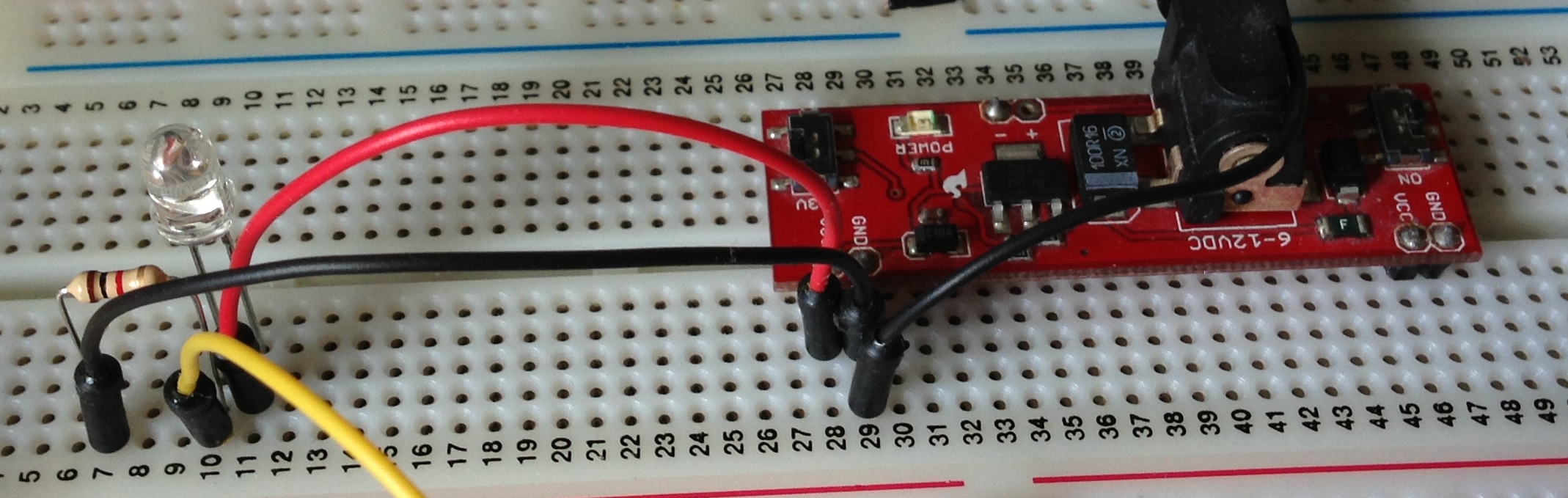
Simple IR Receiver
Connecting the Vout to the oscilloscope and pointing a WD TV remote control at the phototransistor I saw the following trace:
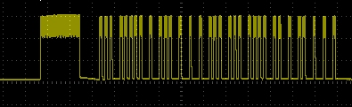
WD TV Remote Signal
So, it looks like the detector circuit is detecting the infra-red signal from these remote controls.
Infra-red Transmitter
The transmitter circuit is simply an infra-red LED with visible LED replaced by an infra-red LED. For this circuit I used the TSUS5400 as this is matched with the L-7113P3C phototransistor I used in the detector circuit. Dropping this into a simple LED/transistor circuit gives the following schematic:
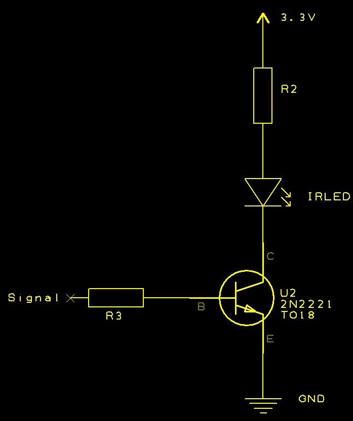
IR Transmitter Schematic
R2 was selected to allow 20mA of current through the infra-red LED (IRLED). The resistor on the base of the transistor should allow the transistor to become saturated. Dropping this on breadboard gives a circuit which looks like this:
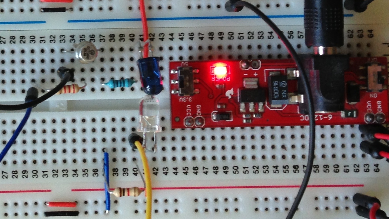
IR Transmitter and Receiver
The top part of the breadboard contains the transmitter circuit (Blue LED) and the lower part of the breadboard contains the receiver.
Testing
To test the circuit a 1KHz signal generator was connected to the base of the transmitter circuit. Channel 1 (yellow) of the oscilloscope is connected to Vout of the receiver with channel 2 (blue) connected to the signal generator. Turning on the signal generator produced the following output on the oscilloscope:
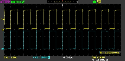
1 KHz Signal
Looking good. The signals show a good match.
Conclusion
The main aim of this exercise was to create an infra-red receiver circuit which can be used to verify that an equivalent transmitter circuit is working. The receiver circuit gives a value for Vout of 3.12V. This is an acceptable value for logic 1 for the microcontrollers which I am using. Their nominal input value for logic 1 is the supply voltage +/- 0.3V.
The transmitter circuit should allow the use of the same microcontroller to generate a signal which can be used to control a device such as a TV etc.
Tags: Electronics, LED
Sunday, August 18th, 2013 at 1:56 pm • Electronics • RSS 2.0 feed Both comments and pings are currently closed.
