Converting The Way of The Register Examples
A few days ago I was discussing a post from this series in the Netduino chat room with someone who is following the posts and is keen to learn about the STM8S. It became apparent that there are a few things I am taking for granted; namely:
- Assuming you all have the same hardware set up as me
- You are familiar with the development environment I am using
For the hardware case this is certainly unlikely especially with the availability and low pricing of the STM8S Discovery boards. As for the software, well there are at least two environments available and a number of compilers and assemblers.
The objective of this post is to describe the environment I am using and how you can convert the hardware and software setup to work with the STM8S Discovery board. By converting the application to this board we will cover the principle steps which should be followed in order to convert the application to run on any of the STM8S family of microcontrollers. We will also cover some of the shortcut keys in the development environment in order to help the novice/infrequent user of the environment become a little more productive.
For the purposes of this exercise we will look at the Simple GPIO example as this application is small and simple.
Hardware
The first thing we will do is look at the hardware I am using and then compare this to the STM8S Discovery board.
My Hardware Configuration
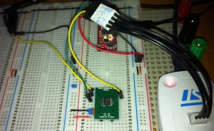
I am using the STM8S103F3P3 in a TSSOP20 package. This has been mounted on a TSSOP20 to DIP board to allow me to insert the chip into a breadboard circuit. When mounting this on a breadboard you need the following components:
- 2 x 1uF capacitors (you can get away with only one for simple circuits)
- 1 x 100nF capacitor
- 3.3V regulated power supply
- ST-Link/V2 programmer
- Some wire to wire it all up.
To put this together, place one of the 1uF capacitors between VSS and VCAP and a 100 nF capacitor is placed between VDD and VSS. An additional (this is the optional capacitor) 1uF capacitor is also placed across the +3.3V and ground of the power supply.
The ST-Link/V2 should be connected to 3.3V and ground with the SWIM and NRST lines connected to the appropriate pins on the STM8S.
When you have all this put together you will have something like the following:
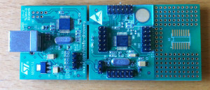
Now compare this to the STM8S Discovery board:
As you can see, all of the work setting up the hardware has been done for you :). You will also note that the chip used is the STM8S105C6T6. This chip is a different series to the one I am targeting. It is also a larger package giving the developer access to more ports etc. This board also has the ST-Link programmer built into the board. The only thing we need in order to use this board is a USB cable.
Development Environment
The development environment we are using is the IAR Kickstarter environment. This allows the creation of small applications (8 KBytes) for the STM8S. At the time of writing, the licence allowed the creation of fully functional applications with no commercial restrictions on the applications you create. The only requirement for the developer is that you register for a licence key.
We will not cover setting up the environment as this is a standard Windows installer.
If you have decided to use this environment then you might want to check out Custom IAR Templates for STM8S Projects. Arron Chapman has also put together some additional files and templates together. These are available in his posting Custome IAR STM8S Template.
Running the Application
We should now have the hardware and software set up so let’s take a look at the application we will be working with:
#include <iostm8S103f3.h>

int main( void )
{
    //
    //  Initialise Port D.
    //
    PD_ODR = 0;             //  All pins are turned off.
    PD_DDR_DDR5 = 1;        //  Port D, bit 5 is output.
    PD_CR1_C15 = 1;         //  Pin is set to Push-Pull mode.
    PD_CR2_C25 = 1;         //  Pin can run up to 10 MHz.
    //
    //  Now lets toggle to IO line.
    //
    while (1)
    {
        PD_ODR_ODR5 = 1;    // Turn Port D, Pin 5 on.
        PD_ODR_ODR5 = 0;    // Turn Port D, Pin 5 off.
    }
}
If you are using the STM8S103F3 chip then the application should compile and deploy OK. So now let’s consider what we need to do to make this run on the STM8S Discovery board.
The first thing to note is the include file we are using. This should match the chip you are using in your environment. You can find a full list of the include files supplied with the development environment in the inc directory of the installation. On my machine these can be found in C:Program Files (x86)IAR SystemsEmbedded Workbench 6.0 Kickstartstm8inc. If you browse through this directory you will find a file iostm8s105c6.h. This is the file you should be using for the STM8S Discovery board.
So make the change to the include file and we can now compile the application (press F7). The application should compile without any warnings or errors.
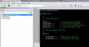
If you were to try to deploy the application now you would receive an error from the development environment. This is because the development environment and the programmer (ST-Link/V2) are targeting the wrong chip. To correct this we need to change the project options. Assuming you have your development environment open you should be looking at something like this:
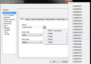
Right click on the project name in the left hand panel (Simple GPIO – Debug) and select Options. Look for the Device text on the dialog which appears and click on the button to the right of the text box which contains the text STM8S103F3P3 and follow the popups which appear and select the STM8S105C6 chip.
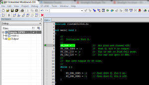
At this point we should be ready to try the application out. So make sure that the STM8S Discovery board is connected to your PC and compile and deploy the application (Ctrl-D). At this point the application compiles and deploys after which the debugger should stop at the default breakpoint which has been set for you on the first line of code. Your display should look something like the following:
The green arrow and the highlighted line indicate the next line of code to be executed. From here we have a few options open to us:
- Run the application with no breakpoints
- Single step through the application
- Set some breakpoints and then run the application
These options should be familiar to any software engineer.
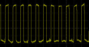
Let’s hook the STM8S Discovery board up to an oscilloscope and run the application (press F5). You should now see the following output on the oscilloscope:
IAR Shortcut Keys
Throughout this post we have looked at some of the shortcut keys which I commonly use. The following table shows the key and the description of its function. This is not meant to be a comprehensive list of the keys used but it covers a few of the basics which I use regularly:
| Key | Function |
| Ctrl-D | Compile the code and deploy to the device. |
| Shift-Ctrl-D | Terminate the debugging session. |
| F7 | Make the project, do not deploy. |
| F5 | In debug mode, causes the application to run until the next breakpoint is reached or the application terminates. |
| F10 | In debug mode, execute the currently selected statement and then break at the next line of code. This will step over any method calls. |
| F11 | As with F10 but this time step into any method calls. |
| Shift-F11 | Step out of the current method being debugged and return to the calling method with a breakpoint set accordingly. |
| Shift-Ctrl-R | Reset the debugging environment setting a breakpoint on the first line of code and restart the application. |
| Ctrl-K | Comment out the currently selected lines of code. |
| Shift-Ctrl-K | Uncomment the selected lines of code. |
Conclusion
As we have shown, a few simple changes to the example code in The Way of the Register series are all we need to make to run these examples on other STM8S chips other than the STM8S103F3. In summary we need to do the following:
- Check the include file and make sure it matches the chip you are using
- Check the chip the development environment is targeting
Hope you have found this useful and continue to enjoy The Way of the Register series.
Tags: Electronics, Software Development, STM8, The Way of the Register
Friday, August 31st, 2012 at 10:47 am • Electronics, Software Development, STM8 • RSS 2.0 feed Both comments and pings are currently closed.