Persistence Of Vision
Saturday, June 11th, 2011By chance last week end I came across a post discussing persistence of vision. This set me wondering if I could demonstrate this using the Netduino. First a little background.
Background
Persistence of vision is the phenomena which allows you to watch a movie. The projector shows a single still image on the screen. This is then replaced 1/24th of a second later by a new image. The projector achieves this by covering the image with a shutter whilst the frame is moved into place. We do not see the blank screen, just the previous frame. A fuller description can be found on this Wikipedia page.
We will be using this effect to control 27 LEDs using only 11 control lines. These lines will be the outputs from two 74595 shift registers which in turn will be connected to a Netduino Plus.
The Problem
The 27 LEDs will be split into three banks of 9. The aim will be to write a small program which will turn on one or more of the of the 9 LEDs in each bank in turn. If we do this slowly we will see bank 1 turn on whilst banks 2 and 3 are off. Next we will see bank 1 turn off, bank 2 will turn on and bank 3 will remain off, and so on. In theory, if we do this fast enough, we will see all three banks on at the same time.
Hardware
This project uses the hardware and principles from two previous projects:
- Netduino Controlling an External LED (using a transistor as a switch)
- Counting Using 74595 Shift Registers
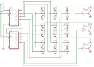
A picture is worth a thousand words so lets have a look at the schematic:
The two shift registers are connected to the Netduino using the SPI interface. The output from IC1 is fed to the serial input of IC2 creating 16 output lines (8 from each register). These lines will power the LEDs and select the bank to turn on.
The LEDs will be powered using bits 0 to 7 of IC1 and bit 0 of IC2.
The top three bits of IC2 will select which bank to turn on. This is done using a transistor as a switch.
The trick to controlling the banks and LEDs lies in the way the circuit is wired up. The anodes of LED1, LED10 and LED19 are connected together and then connected to QA of IC1. Similarly, the anodes of LED2, LED11 and LED20 are connected to QB of IC1. This continues until all 27 LEDs have been connected to the 9 control lines (QA-QH of IC1 and QA of IC2).
The next part of the trick is to connect the cathodes from the LEDs in bank 1 together. These are then connected to a current limiting resistor which is in turn connected to the collector of a 2N2222 NPN transistor. This is repeated with banks 2 and 3 being connected similarly to their own transistor.
The base of each transistor is connected through a resistor to one of the bank control outputs pins (QF, QG and QH) of IC2. The emitter is connected to ground.
Note that in theory it is possible to turn on all three banks at once by setting the appropriate bits in the shift register but the object of this exercise is to show how to make a still image using each bank in turn.
Software
The software uses SPI to send two bytes to the 74595 shift registers. The values sent will control which LEDs are turned on / off. The code looks like this:
SPI.Configuration config;
config = new SPI.Configuration(SPI_mod: SPI.SPI_module.SPI1, ChipSelect_Port: Pins.GPIO_PIN_D9, ChipSelect_ActiveState: false, ChipSelect_SetupTime: 0, ChipSelect_HoldTime: 0, Clock_IdleState: true, Clock_Edge: false, Clock_RateKHz: 400);
SPI spi = new SPI(config);
byte[] value = new byte[2];
value[1] = 0xff;
while (true)
{
    value[0] = 0x81;
    spi.Write(value);
    value[0] = 0x41;
    spi.Write(value);
    value[0] = 0x21;
    spi.Write(value);
}
If you run this code you will see a still image with all three banks looking as though they are permanently on. Set a breakpoint on the line value[0] = 0x81; and run the program again. Single stepping will show each bank being turned on in turn. The reason we see the still image is because the banks are turned on and off quickly.
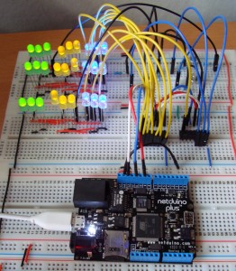
Putting it all together and wiring it up on breadboard gives you this:


