RSS

Archive for the ‘STM8’ Category

STM8S Interrupts With the STD Peripheral Library

Saturday, May 12th, 2012

So you have just purchased that wonderful sensor and now need it to grab the attention of the STM8S – enter the interrupt. In this post I will run through how to set up a GPIO port to have an incoming logic signal generate an interrupt.

As in previous posts on the STM8S, this post will use the IAR development environment and the STD Peripheral Library from ST.

Configuring the Port

The first step is to configure a port for input. The following code configures a pin on GPIOB for input:


GPIO_DeInit(GPIOB);
GPIO_Init(GPIOB, GPIO_PIN_5, GPIO_MODE_IN_FL_IT);

the next thing we need to do is to tell the system that this pin is allowed to generate an interrupt:


EXTI_SetExtIntSensitivity(GPIOB, 
                          EXTI_SENSITIVITY_RISE_ONLY);

So that should be all that’s required to configure the system to accept interrupts. Now we just need to process them.

Interrupt Handler

If you have followed my previous posts you will know that we need to copy some standard files across in order to access the STD Peripheral Library. One of the files we add to the project is stm8s_it.c. This holds the interrupt table for the chip. Scroll through the file and you will eventually reach some code which looks like this:


INTERRUPT_HANDLER(EXTI_PORTB_IRQHandler, 4)
{
  /* In order to detect unexpected events during development,
     it is recommended to set a breakpoint on the following instruction.
  */
}

Just place the code to be executed in this method. Remember, interrupt handlers should be small and concise.

Modules

This post requires that you add the code files for the following STD Peripheral Library modules:

  • stm8s_gpio.c
  • stm8s_exti.c

Conclusion

A relatively short post but there’s not much too it. I have successfully used this code to generate an interrupt from a sensor which generates a square wave of up to 500 KHz. The conditions I was using it in gave a maximum frequency of 20 KHz.

STM8S Timers

Saturday, May 12th, 2012

This post has been superseded by the post Using Timers on the STM8S in The Way of the Register series.

In the first post about this chip I showed how the internal clock could be output on a single pin. Here I am going to use one of the internal timers to generate my own clock signal. So in this post we will use two new concepts:

  • GPIO pins to output a signal.
  • Timer 2 to control the timing
  • Interrupt Service Routines (ISR) to do the work

The program will work by setting up timer 2 to generate an interrupt on a regular basis. When the timer interrupt fires we will reverse the direction of a GPIO pin. The net result will be a clock signal with a frequency of twice that of the timer.

As with the previous post I will be using the IAR environment with the STD Peripheral Library.

Setting up the GPIO

The application sets up the GPIO port using the following code:

#define CLOCK_OUTPUT_PORT       GPIOD
#define CLOCK_OUTPUT_PIN        GPIO_PIN_3

These #defines hold the port and pin numbers we are going to use for the clock signal. So in this case we are using pin 3 on port D. Next we need to configure the port.

GPIO_DeInit(CLOCK_OUTPUT_PORT);
GPIO_Init(CLOCK_OUTPUT_PORT, CLOCK_OUTPUT_PIN, GPIO_MODE_OUT_PP_LOW_FAST);

The first statement resets the port so that we can configure the port. The second sets up pin 3 of port D for use. Note that you can use each pin on a port in a different way, so we could have pin 2 on port D as an input whilst pin 3 is an output. To do this you simply add more GPIO_Init statements under the first. Now let’s have a look at the final parameter to the GPIO_Init statement. This defines how the pin will be set up for us. You can decode this as follows:

  • GPIO_MODE_OUT – this is an output port
  • PP – the pin will be used in Push-Pull (as opposed to open drain). This means Setting the pin to 1 will make the pin high, setting it to 0 will make it low.
  • LOW – the pin will start out low
  • FAST – the pin will be used for fast signalling.

Setting up Timer 2

Next step is to configure the timer to interrupt on a regular basis. The first step is to set up the clock to use a known clock signal. For simplicity we will set this up to use the internal high speed clock source which runs at 16MHz. This code is similar to the code in the first post.

CLK_DeInit();
CLK_SYSCLKConfig(CLK_PRESCALER_CPUDIV1);                // CPU Prescaler = 1.
CLK_SYSCLKConfig(CLK_PRESCALER_HSIDIV1);                // Prescaler = 1, 16 MHz.
CLK_ClockSwitchConfig(CLK_SWITCHMODE_AUTO,              // Automatically switch
                      CLK_SOURCE_HSI,                   // Switch to internal timer.
                      DISABLE,                          // Disable the clock switch interrupt.
                      CLK_CURRENTCLOCKSTATE_DISABLE);   // Disable the previous clock.

The only real difference is that the prescaler for the system clock is set to 1 to give the full clock speed.

The next task is to set up the timer to run at a particular frequency:

TIM2_DeInit();
TIM2_TimeBaseInit(TIM2_PRESCALER_4096,      // Interrupt every 4096 clock pulses.
                  1);                       // Period is one.
TIM2_ITConfig(TIM2_IT_UPDATE, ENABLE);      // Enable the overflow interrupt.
TIM2_Cmd(ENABLE);

The comment interrupt every half millisecond is approximate as you will see when we come to take some measurements later.

The Interrupt Service Routine

The final piece of the puzzle is the interrupt service routine. These should always be small and fast. In this case we will simply toggle the specified clock pin to generate a clock signal.

All of the ISR’s are defined in the file stm8s_it.c. The ISR we will be working with is the timer 2 update overflow handler. This will fire when the counter for the timer overflows or becomes zero and the specified number of occurrences of this event have occurred. So in this file we need to locate this code:

INTERRUPT_HANDLER(TIM2_UPD_OVF_BRK_IRQHandler, 13)
{
}

and translate it to this:

INTERRUPT_HANDLER(TIM2_UPD_OVF_BRK_IRQHandler, 13)
{
    GPIO_WriteReverse(CLOCK_OUTPUT_PORT, CLOCK_OUTPUT_PIN);     // Generate a clock signal.
    TIM2->SR1 = (uint8_t) (~(uint8_t) TIM2_IT_UPDATE);          // Clear the interrupt.
}

The first line of the ISR toggles the specified bit. The second line is important as this clears the interrupt. If we do not do this then the system will return to this ISR as soon as we exit the routine.

Clock Signal

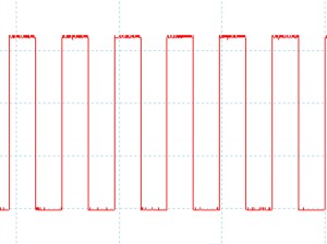
Compiling and deploying this code to the processor results in the following output on pin 3 of port D:

One millisecond clock signal on port D, pin 3.

The scope we set up for 2 milliseconds per division and this looks about right. The exact frequency count comes out to be 976.6 Hz which is right if you divide the clock signal by the prescaler.

Connecting up the STM8S003

Sunday, April 29th, 2012

A few days ago I wrote about my first attempt at coding for the STM8S003 but forgot to mention how I connected up the chip to the PC. So here is a quick post explaining how to do it.

The STM8S Chip

The STM8S chip chosen was the STM8S003F3 in a TSSOP20 package. This form factor is incredibly small and there is no way to mount it on a breadboard without some for of adapter. Luckily Sparkfun have a SSOP to DIP Adapter 20-Pin in their catalog. However, I could not get hold of one in the UK so I ended up getting the 28 pin version instead. A bit of a waste but it worked.

So armed with the adapter, a chip and some connectors it was time to break out the soldering iron. A brief experiment with drag soldering did not work and I finally settled on soldering each pin very carefully with the finest soldering iron tip I had.

STM8S on SSOP to DIP Adapter

The next job was to mount all of this on the breadboard. There are only really two additional components required for this circuit, 1uF and 0.1uf ceramic capacitors. You can see both of these to the left of the chip in the above picture. The 0.1uf capacitor connects ground and +3.3V and acts as a power smoothing capacitor. The 1uF capacitor connects Vcap and ground.

ST-Link/V2 Programmer and Debugger

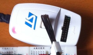
The chip is programmed using the low cost (£20 approx) ST-Link/V2 programmer and debugger. This works with both the STM8 and STM32 range of processors.

ST-Link/V2 Programmer Debugger

Putting it all Together

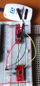
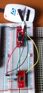
If we put the two components together we get something which looks like this:

STM8S On Breadboard

The red PCB between the programmer and the STM8S circuit is a breadboard power supply which has been set to supply 3.3C to the circuit. The wires connecting the STM8 to the programmer are as follows:

Colour Description
Red Power (3.3V)
Black Ground
Green Reset
Yellow Data

Netduino Go! Module Development – the First Steps

Friday, April 27th, 2012

The last few weeks I’ve been getting things together to start to look at developing a smart module for the Netduino GO!. This post looks at the first steps and ends up with some working code on a STM8S003 chip.

STM8S Discovery

My starting point was to get the software tools installed and working. In order to verify this I purchased the STM8S Discovery board. This has the STLink module and a STM8S105 microcontroller built into a convenient package for less than £7.00. This board itself was easy to set up and worked straight out of the box.

Development Environment

Having the board is one thing but we need a development environment to work with. I tried several environments and in the end I found I was happiest with the IAR environment so for the moment I’m sticking with it whilst I find my feet. Set up was easy and it found the STM8S Discovery straight away.

Start With Something Simple

I wanted to start with a really simple project which would not require any additional hardware other than a scope to check that the application was working. That way I could transfer the program to a microcontroller on a breadboard and know that I had as few possible points of failure as possible. To this end I decided that I would put the microcontroller clock pulses out on one of the pins. I could verify that everything was working but uploading a new program which changed the clock scaler and if all was well I would see a different trace on the scope.

This choice of application was no accident as the data sheet for the chip shows that it has a pin labelled CCO. You can configure this pin to output the controller’s clock signal. Not only that but you can also use the microcontroller’s internal clock generator as the clock signal. So in theory, all I needed to do was add a few discrete components to the breadboard along with the STM8S and I should have a small, simple, self contained system to test the tool set.

Creating a New Project

First thing to do is create a new workspace and project using IAR. Simple enough, enter a name for both and a new main.c is presented to you. Good game but not much use as it stands.

Luckily ST provide a standard library of drivers for the various features available on their chip sets. I downloaded version 2.1.0 of the library and this contained the drivers and some sample applications. The trick is to understand the way in which you access the libraries. It’s really simple and basic. In effect, you add the C source files for the library to your application and compile your application and the libraries at the same time. Both of these are then deployed as a single binary to the microcontroller. Basic but it works. The source files are broken down by microcontroller feature. So, all of the routines etc. for timer 2 are in the header file stm8s_tim2.h and the source code is in the file stm8s_tim2.c.

To make things easier (well, easier for me anyway) I have taken to copying the source and include files from the standard library provided into each project directory I create. That way you simply need to add the source file for a feature as you need it. In this case the only feature I’m going to be using is the clock and so I need to make sure I add the stm8s_clk.c file to the project.

The stm8s.h file contains definitions for a whole range of controllers. It is therefore necessary to define a preprocessor macro for the type of controller the application is targeting. This can be done in one of two ways, either in the stm8s.h file itself (as this in included in the other standard library files) or as a macro in the project. I personally prefer to do this in the project as it makes updating the library code easier.

So Let’s Get Started

First thing to do is to get a workspace and project created. So open IAR and create a new workspace. Next, go to the Project Menu and create a new project. The following dialog should appear:
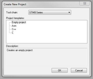
New Project Dialog

Select a C project and click OK. The next dialog asks you to select a name and location for the project. So decide on a location and name. Being very creative, I went for Test as the project name. Once completed I had a project which looked like this:
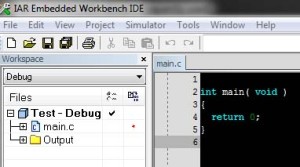
New C Project.

The next job is to add the include and source files for the standard peripheral library. So copy the include and source files from the library and add them to the directory containing your project. I normally put the include files in the inc directory and the sources in the src directory. The next thing to do is add these files to the project. So right click on the project name (in this case Test – Debug and select Add – Add Group. Enter the name STD Peripheral Include
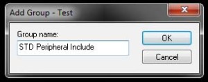
Add new file group

Repeat this to add the source file group with the name STD Peripheral Source. Your project should now look like this:
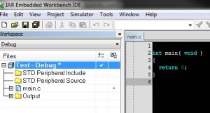
File Groups Added to Project

Now we need to add the files to the groups. For the include files I add all of the files. For the source files I only add the ones I will be using. To do this you right click on one of the file groups we have created, say the STD Peripheral Include group and select Add – Add Files…. For the include files navigate to the directory containing the copied files and select them all.

Repeat for the source files but this time we only select the files we will be using. In this case the clock file stm8s_clk.c. Your project should now look something like this:
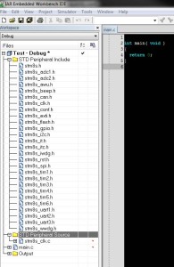
All Files added

There are still a few extra steps before we can write some code. The STM8S include files require that the type of chip is defined before any code will compile so we will need to define a preprocessor macro indicating which chip we are using. Next we need to tell the compiler about the location of the include files. Finally, we need to tell the system how to deploy and debug the application.

So let’s start off with the chip family. Firstly we want to tell the compiler about the target family. So right click on the project name and this time select Options. Under General options, select the chip family to be targeted. For the Discovery board the family is STM8S105, for the final module we will be targeting the STM8S003.
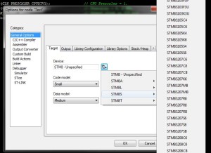
Select chip family.

The next step is to tell the preprocessor about the chip family and the location of the include files. From the same dialog as above, select the C/C++ compiler and the Preprocessor tab. Add the entry $PROJ_DIR$inc to the include files and define a symbol for the chip set. Define STM8S105 for the Discovery board and STM8S003 for the final module.
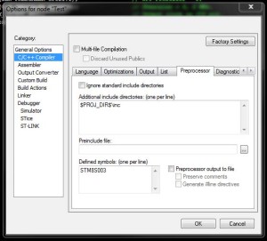
Pre-processor Options

The final step is to tell the IDE how to deploy and debug the application. From the Options dialog select the Debugger category and set the Driver to ST-LINK.
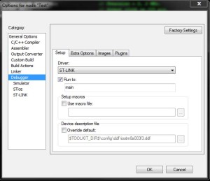
Debugger Options.

Now click on OK to set the options. We can now start to write some code.

Let’s Write Some Code

Replace the code in the main.c file with the following:

#include "stm8s.h"
#include "stm8s_clk.h"

int main(void)
{
    CLK_DeInit();
    CLK_SYSCLKConfig(CLK_PRESCALER_CPUDIV1);                // CPU Prescaler = 1.
    CLK_SYSCLKConfig(CLK_PRESCALER_HSIDIV8);                // Prescaler = 8, 2 MHz.
    CLK_CCOConfig(CLK_OUTPUT_HSI);                          // Output clock on CCO pin.
    CLK_ClockSwitchConfig(CLK_SWITCHMODE_AUTO,              // Automatically switch
                          CLK_SOURCE_HSE,                   // Switch to internal timer.
                          DISABLE,                          // Disable the clock switch interrupt.
                          CLK_CURRENTCLOCKSTATE_DISABLE);   // Disable the previous clock.
}

Connect up board/chip and hit Ctrl-D. This will compile and deploy the application. The debugger should start with the first line of main highlighted. Press F5 and the application should start. Hooking up the oscilloscope gave the following trace:
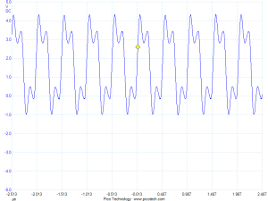
Oscilloscope Output

The clock frequency of the chip using the internal high speed oscillator is 16 MHz. Diving this by 8 should give a 2 MHz signal (as indeed the above trace shows). Just to check if this is a coincidence, change to CLK_PRESCALER_HSIDIV8 to say CLK_PRESCALER_HSIDIV4 and the scope output should change to show the new clock frequency and sure enough it does.