Bare Metal GPIO on the Raspberry Pi
The Raspberry Pi is classically used as a single board computer running Linux but it also offers the possibility of using the board without Linux (known as bare metal development). Add to this the availability of free ARM development tools and we have the opportunity to develop on a high speed ARM processor at a reasonable cost.
This post explores the steps necessary to toggle a GPIO pin on the Raspberry Pi by directly accessing the registers without the presence of an operating system.
Project Description
For this simple project the software will need to perform three operations:
- Configure the GPIO port
- Set the GPIO pins for the selected port
- Reset the GPIO pins for the selected port
The application here will toggle two GPIO pins, one connected to one of the LEDs on the board (GPIO16 connected to the OK/ACT LED) and the second connected to a pin on the header (GPIO18 connected to Pin 12 on header P1).
Resources
There are already a number of resources out on the internet which cover this topic including a large number references in the Bare Metal forum on the Raspberry Pi web site.
As well as the Raspberry Pi web site there are a number of other sites discussing OS development for the Raspberry Pi. This post was going to be a comprehensive write up of the tools and various scripts required to put together a bare metal example but I have since discovered an excellent tutorial on this subject on the OSDev web site. I would heartily recommend that you visit this web site and review the material on the Raspberry Pi C Tutorial page.
Hardware
Before we look at the registers we need to take a look at the first chapter of the Broadcom BCM2835 ARM Peripheral document. Particularly the following two paragraphs:
Physical addresses range from 0x20000000 to 0x20FFFFFF for peripherals. The bus addresses for peripherals are set up to map onto the peripheral bus address range starting at 0x7E000000. Thus a peripheral advertised here at bus address 0x7Ennnnnn is available at physical address 0x20nnnnnn.
and
The peripheral addresses specified in this document are bus addresses. Software directly accessing peripherals must translate these addresses into physical or virtual addresses, as described above. Software accessing peripherals using the DMA engines must use bus addresses.
The remainder of the document discusses the registers and uses addresses in the 0x7Ennnnnn-0x7EFFFFFF memory range. This means that any software written should translate the 0x7Ennnnnn range down to the 0x20nnnnnn range.
GPIO Configuration Register
The software will need to set the function for GPIO pins 16 and 18 using the function select registers. The description of these registers and the GPIO pins which they relate to can be found on page 92 of the Broadcom BCM2835 ARM Peripheral manual. The port is configured using three bits in the register. The three bits have the following meaning:
| Bit Field | Description |
| 000 | GPIO Pin is an input |
| 001 | GPIO Pin is an output |
| 100 | GPIO Pin configured for alternate function 0 |
| 101 | GPIO Pin configured for alternate function 1 |
| 110 | GPIO Pin configured for alternate function 2 |
| 111 | GPIO Pin configured for alternate function 3 |
| 011 | GPIO Pin configured for alternate function 4 |
| 010 | GPIO Pin configured for alternate function 5 |
The two pins the software will be accessing are pins 16 and 18. These pins are configured using bits 24-26 for GPIO 18 and 18-20 for GPIO 16 of the GPFSEL1 register at 0x7E200004. This maps to the address 0x20200004.
Set GPIO Pin High
The GPIO pins are set by setting a bit in the GPSETn registers. Both GPIO16 and GPIO18 are set through the GPSET0 register (see page 95 of the Broadcom BCM2835 ARM Peripheral manual). The address of this register is 0x7E20001C (0x2020001C).
Set GPIO Pin Low (Clear the GPIO Pin)
The GPIO pins are reset by setting a bit in the GPCLRn registers. Both GPIO16 and GPIO18 are set through the GPCLR0 register (see page 95 of the Broadcom BCM2835 ARM Peripheral manual). The address of this register is 0x7E200028 (0x20200028).
Software
The application is a relatively simple one, toggling a GPIO pin continuously. The following should suffice:
//
//  Flags used to configure the GPIO port.
//
#define FLAG_GPIO_RESET     ((7 << 18) | (7 << 24))
#define FLAG_GPIO_CONFIG    ((1 << 18) | (1 << 24))
//
//  Bits which will allow control of GPIO0 pins for the status
//  LED and the header on the Pi.
//
#define GPIO_PINS           ((1 << 16) | (1 << 18))
//
//  The following register definitions are used to access the GPIO
//  pins on the BCM2835.  The register definitions are taken from
//  section 6 of the BCM manual and the mapping is described in
//  section 1 of the same.
//
//  Address of the register which will configure the GPIO pins.
//
volatile unsigned int *gpsel1 = (unsigned int *) 0x20200004;
//
//  Address of the register which will set the GPIO pins.
//
volatile unsigned int *gpset0 = (unsigned int *) 0x2020001C;
//
//  Address of the register which will clear the GPIO pins.
//
volatile unsigned int *gpclr0 = (unsigned int *) 0x20200028;
//
//  Contents of the GPIO configuration register.
//
unsigned int gpioConfig;
//
//  Main program loop.
//
int main()
{
    //
    //  Reconfigure GPIO 16 and 18 to be outputs.  Clear any
    //  previous GPIO configuration for these pins.
    //
    gpioConfig = *gpsel1;
    //
    //  Firstly, remove any configuration for GPIO 16 & 18.
    //
    gpioConfig &= ~FLAG_GPIO_RESET;
    //
    //  Now configure GPIO 16 & 18 to be plain GPIO outputs.
    //
    gpioConfig |= FLAG_GPIO_CONFIG;
    *gpsel1 = gpioConfig;
    //
    //  Toggle GPIO 16 and 18 forever.
    //
    while (1)
    {
        *gpclr0 = GPIO_PINS;
        *gpset0 = GPIO_PINS;
    }
    return(0);
}
The makefile I used to build the application looks as follows:
#
#   Root directory/name of the ARM tools used to build the application.
#
ARMTOOLSROOT = e:\utils\gcc-arm\bin\arm-none-eabi

#
#   C Compiler options.
#
OPTIONS = -nostdlib -ffreestanding -O3

#
#   What do we need to make to build everything?
#
all: kernel.img
    copy /y /d kernel.img j:\

HelloWorldBlinky.o : HelloWorldBlinky.c
	$(ARMTOOLSROOT)-gcc $(OPTIONS) -c HelloWorldBlinky.c -o HelloWorldBlinky.o

HelloWorldBlinky.elf : memmap HelloWorldBlinky.o
	$(ARMTOOLSROOT)-ld HelloWorldBlinky.o -T memmap -o HelloWorldBlinky.elf
	$(ARMTOOLSROOT)-objdump -D HelloWorldBlinky.elf > HelloWorldBlinky.list

kernel.img : HelloWorldBlinky.elf
	$(ARMTOOLSROOT)-objcopy HelloWorldBlinky.elf -O binary kernel.img

#
#   Delete any previously built files.
#
clean :
	del -f HelloWorldBlinky.o
	del -f HelloWorldBlinky.elf
	del -f HelloWorldBlinky.list
	del -f kernel.img
Tools
The software present here was compiled using the version 4.8.3 of the ARM eabi tools.
Conclusion
Compiling the above code and executing the application results in the following output when the oscilloscope is connection to GPIO18:
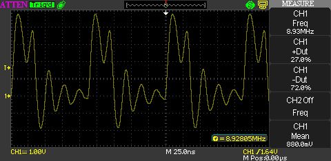
Raspberry Pi GPIO Output
It is necessary to review the documents in the resources section of this post in order to fully understand the theory behind this application.
And now it is time to take on some more complex topics.
Tags: Electronics, Raspberry Pi, Software Development
Monday, June 16th, 2014 at 6:45 pm • Electronics, Raspberry Pi, Software Development • RSS 2.0 feed Both comments and pings are currently closed.
Really interesting article, takes me back to my embedded software days in the late 80s writing real time code on Intel 8031s!
I suppose it just goes to show the world domination that the RPi now has over the Arduino as the costs are similar but the processing power is not.
If you are looking for any ideas for your more complex topics, a bootstrapper would be good!
It started out as a longer article as I was going to describe more about the booting and linking process but the article http://wiki.osdev.org/ARM_RaspberryPi_Tutorial_C does an excellent job of it. In fact it does a better job of it than I was going to do.
I have found another article on the OSDev web site which discusses loading firmware over a serial port: http://wiki.osdev.org/ARM_RaspberryPi Something to look at later.
Last time I bootstapped anything it was a FORTRAN77 compiler when I ported it from Unix to Windows NT 3.1 way back in 1992.
Regards,
Mark