Netduino, iPhone and Low Energy Bluetooth
Saturday, August 24th, 2013A while ago I wrote a small library for the RN-42 Bluetooth module. This small module acted as a serial port when connected to the Netduino. Times have moved on with Bluetooth 4.0 being available on the iPhone I thought I would take another look at Bluetooth.
Bluetooth Module
The Bluetooth module we will be using is the RedBear Bluetooth Mini. This little module is a Bluetooth 4.0 Low Energy (BLE) module. In it’s simplest form it offers the ability to act as a serial port for your project. This is how we will be using this module for this project.
Bluetooth Device
To test this a BLE compatible device is required. Enter the iPhone 5 and the BLE Arduino application which RedBear have thoughtfully provided. The application may be written for Arduino but it is sending simple serial commands to the Arduino. Let’s see what it is doing and if we can use this application.
Serial Port Settings
First job is to figure out the serial port settings. Scanning the source code for the Arduino I came across the following line in the setup method:
BleFirmata.begin(57600);
My guess is that this is setting up the Arduino serial port to run at 57,600 baud using standard data bits, parity and top bit settings. Time to break out the logic analyser.
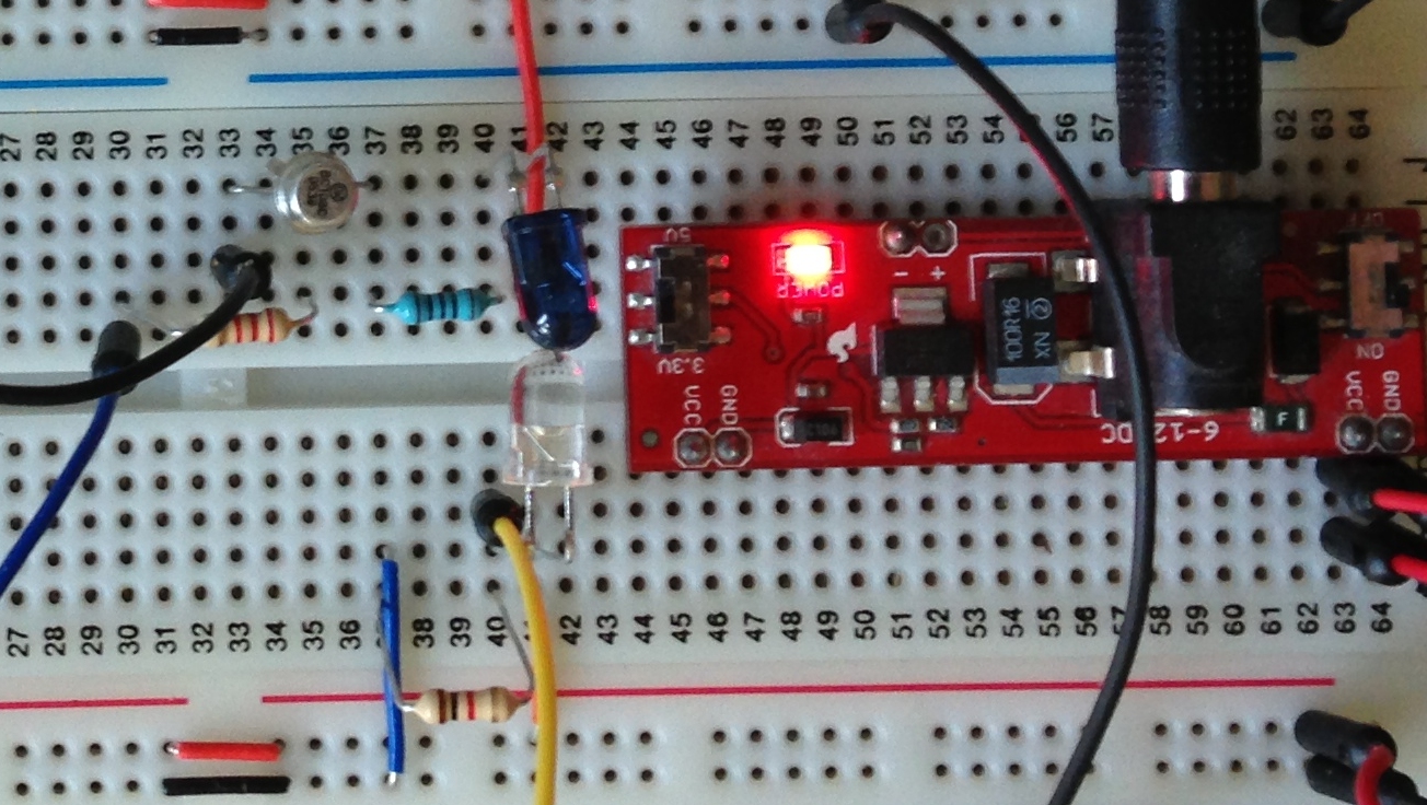
Connections between the Netduino and the RedBear module is simple:
| Netduino Pin | Redbear BLE Module Pin |
| D0 (Rx) | Tx |
| D1 (Tx) | Rx |
| 3.3V | Vin |
| GND | GND |
Additionally, the logic analyser is connected to the Rx and Tx pins of the Netduino. An Async Serial analyser was added to the two pins through the Saleae software. This analyser has an Autobaud feature. Turn this on just in case we get the baud rate incorrect.
Next step is to install the BLE Arduino application on the iPhone 5. Start the application:

ReadBear BLE Software Opening Screen
Press the Click button to connect to the ReadBear module.
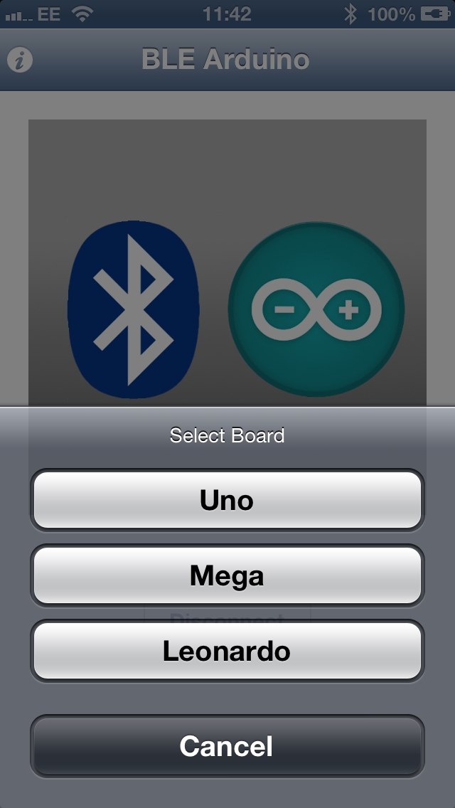
Select Arduino Board
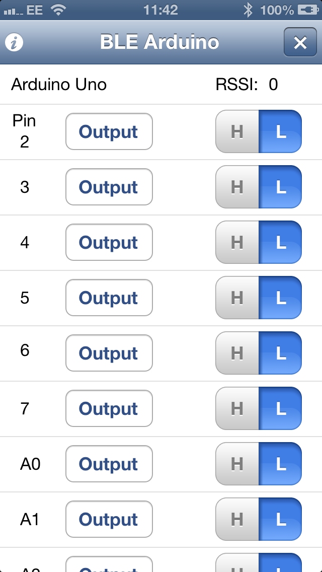
Change a Pin Output Using BLE Software
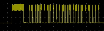
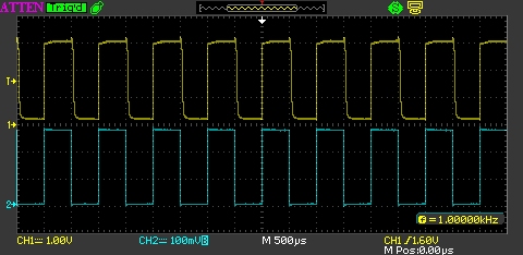
So far there has been no output on the logic analyser. Change the state of an output pin (pressing H or L). This generates serial data:
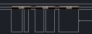
Serial Data On the Logic Analyser
A quick check in the Async Serial analysers properties shows that the data logic analyser thinks that the data is being sent at 60,000 baud, pretty close to the 57,600 which was found in the code earlier.
Netduino Code
The next step is to try to connect some code on the Netduino to the iPhone application. The simplest application we can use simply captures the incoming data on the serial port and displays the bytes received in the debug window of Visual Studio. The following should do the trick:
public class Program
{
    const int BUFFER_SIZE = 1024;

    public static void Main()
    {
        SerialPort sp = new SerialPort("COM1", 57600, Parity.None, 8, StopBits.One);
        sp.DataReceived += sp_DataReceived;
        sp.Open();
        Thread.Sleep(Timeout.Infinite);
    }

    static void sp_DataReceived(object sender, SerialDataReceivedEventArgs e)
    {
        string str;
        str = "";
        if (e.EventType == SerialData.Chars)
        {
            int amount;
            byte[] buffer;

            buffer = new byte[BUFFER_SIZE];
            amount = ((SerialPort) sender).Read(buffer, 0, BUFFER_SIZE);
            if (amount > 0)
            {
                for (int index = 0; index < amount; index++)
                {
                    str += buffer[index].ToString();
                    str += " ";
                }
                Debug.Print("Data: " + str);
            }
        }
    }
}
Deploying the above code to my Netduino Plus 2 and running the application gives the following output:
Data: 144 4 0

Data: 144

Data: 12 0

Data: 144

Data: 4 0
Pressing the H at the side of Pin 2 in the application generates the sequence 144 4 0. Following this up by pressing the H at the side of Pin 3 results in the sequence 144 12 0. Checking the Arduino code shows that the digital commands are prefixed by 0x90, i.e. 144.
The iPhone Application
Now that we know the iPhone and the Netduino can communicate (at least from the phone to the Netduino) let’s have a look at creating our own iPhone application. The simplest application would entail toggling a digital pin, so let’s do that. We’ll turn an LED on and off.
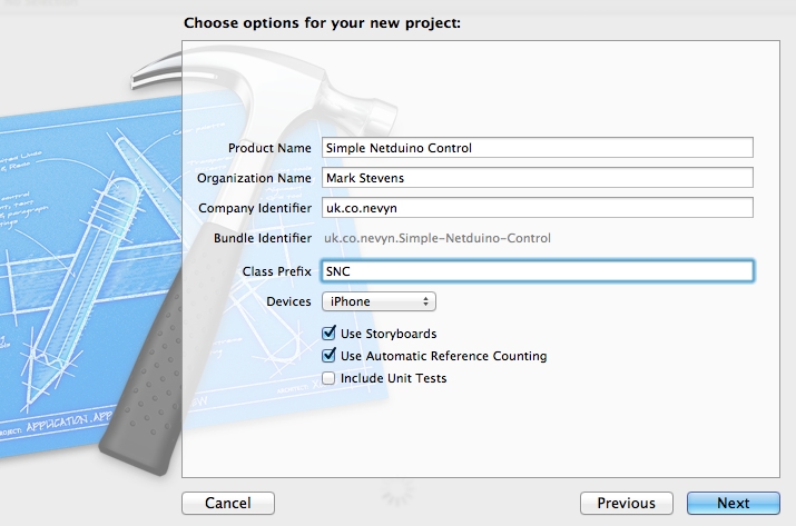
Starting XCode we will create a new project (Single View Application) for the iPhone and set the application be targeted at the iPhone only and to use Automatic Reference Counting (ARC):
New iPhone Project Options
Next we need to add the CoreBluetooth.Framework references to the application. So scroll down the frameworks and click on the + button under the Linked Frameworks section. Type bluetooth in order to search the installed frameworks.
Next, we need to add the RedBear BLE framework. I downloaded this and put it in my stored libraries. This was then added by right clicking on the Frameworks folder of the project, selecting Add Files to… and then browsing to the folder which contained the files.
Next we head over to the Storyboard and add a few controls to our interface:
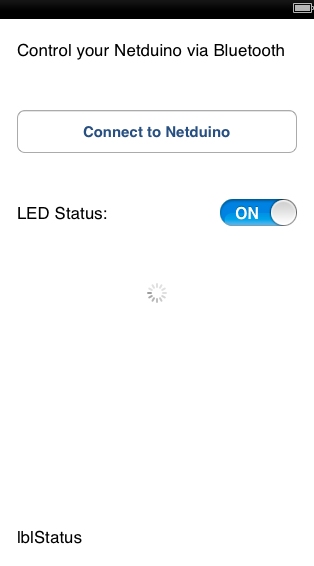
iPhone Application in XCode
| Control | Description |
| btnConnectToNetduino | Button to connect/disconnect to/from the Netduino. |
| lblStatus | Label to indicate the status of the application. |
| lblLEDStatus | Label containing the text LED Status |
| swLED | Switch which is used to turn the LED on/off. |
| aiBusy | Indicator which shows when the application is trying to detect the Bluetooth module. |
First thing to do is to connect the controls to the code in the header file for the view controller:
#import <UIKit/UIKit.h>
#import "BLE.h"

//
//  Define the various modes for the state machine.
//
#define MODE_DISCONNECTED       0
#define MODE_CONNECTING         1
#define MODE_CONNECTED          2
#define MODE_DISCONNECTING      3

//
//  Timeout values.
//
#define TIMEOUT_BLE_TIMEOUT         2
#define TIMEOUT_BUSY_CONNECTING     3.0

@interface SNCViewController : UIViewController <BLEDelegate>
{
    IBOutlet UILabel *lblStatusMessage;
    IBOutlet UILabel *lblLEDStatus;
    IBOutlet UISwitch *swLED;
}

- (IBAction) btnConnect_TouchUpInside:(UIButton *) sender;
- (IBAction) swLED_Changed:(UISwitch *)sender;

@property (strong, nonatomic) BLE *ble;
@property (strong, nonatomic) UIActivityIndicatorView *aiBusy;
@property (strong, nonatomic) IBOutlet UIButton *btnConnectToNetduino;

@end
Now we have the controls defined in the header file we can start to work on the methods.
Definitions
We need some simple definitions at the head of our implementation file:
#import "SNCViewController.h"
#import "BLE.h"

@interface SNCViewController ()

@end

@implementation SNCViewController

@synthesize ble;
@synthesize btnConnectToNetduino;

//
//  Private local variables.
//
int mode = MODE_DISCONNECTED;
These definitions create the Bluetooth object and he variables required for state control.
Supporting Methods
The Connected and Disconnected methods change the interface and state variables when we have successfully connected or disconnected to/from the Bluetooth module:
//
//  Set up the interface to show that the Bluetooth module is connected
//
- (void) Connected
{
    [lblStatusMessage setText:@"Connected"];
    lblLEDStatus.hidden = false;
    swLED.hidden = false;
    [btnConnectToNetduino setTitle:@"Disconnect from Netduino" forState:UIControlStateNormal];
    btnConnectToNetduino.enabled = true;
    [self.aiBusy stopAnimating];
    mode = MODE_CONNECTED;
}

//
//  Set up the interface to show that the Bluetooth module is disconnected
//
- (void) Disconnected
{
    [lblStatusMessage setText:@"Disconnected"];
    lblLEDStatus.hidden = true;
    swLED.hidden = true;
    [btnConnectToNetduino setTitle:@"Connect to Netduino" forState:UIControlStateNormal];
    btnConnectToNetduino.enabled = true;
    [self.aiBusy stopAnimating];
    mode = MODE_DISCONNECTED;
}
Standard Methods (viewDidLoad and didReceiveMemoryWarning)
These methods are generated by default when the application is first created. For viewDidLoad we will set up the application for initial use. We will not be modifying the didReceiveMemoryWarning method in this application.
//
//  Setup the view.
//
- (void) viewDidLoad
{
    [super viewDidLoad];
    //
    //  Setup the display.
    //
    lblLEDStatus.hidden = true;
    [swLED setOn:NO];
    swLED.hidden = true;
    [lblStatusMessage setText:@"Ready"];
    self.aiBusy.hidesWhenStopped = true;
    //
    //  Create the Bluetooth objects.
    //
    ble = [[BLE alloc] init];
    [ble controlSetup:1];
    ble.delegate = self;
    //
    //  Setp the simple properties.
    //
    mode = MODE_DISCONNECTED;
}

//
//  Process the memory warning event.
//
- (void) didReceiveMemoryWarning
{
    [super didReceiveMemoryWarning];
}
The main point to note in the viewDidLoad method is that the Bluetooth object is initialised.
Button Press Event
The btnConnect_TouchUpInside event initiates the connection/disconnection of the application to/from the Bluetooth module.
//
//  User has pressed the Connect button so try to connect/disconnect from the Netduino.
//
- (IBAction) btnConnect_TouchUpInside:(UIButton *) sender
{
    if (ble.activePeripheral)
    {
        if (ble.activePeripheral.isConnected)
        {
            [[ble CM] cancelPeripheralConnection:[ble activePeripheral]];
        }
    }
    ble.peripherals = nil;
    switch (mode)
    {
        case MODE_DISCONNECTED:
            [lblStatusMessage setText:@"Connecting..."];
            [NSTimer scheduledTimerWithTimeInterval:(float) TIMEOUT_BUSY_CONNECTING target:self selector:@selector(connectionTimer:) userInfo:nil repeats:NO];
            [ble findBLEPeripherals:TIMEOUT_BLE_TIMEOUT];
            [self.aiBusy startAnimating];
            mode = MODE_CONNECTING;
            break;
        case MODE_CONNECTED:
            [lblStatusMessage setText:@"Disconnecting..."];
            [self.aiBusy startAnimating];
            mode = MODE_DISCONNECTING;
            break;
        default:
            break;
    }
    btnConnectToNetduino.enabled = false;
}
Timer
The btnConnect_TouchUpInside event starts a timer when it is trying to connect to a Bluetooth module. This timer prevents the application from locking when searching for a Bluetooth module which does not exist. The timer callback stops the search process after 3 seconds:
//
//  The timer started by the Connect button has triggered.  See if we have any
//  Bluetooth modules nearby.  If we have then connect to the first one in the
//  list.
//
-(void) connectionTimer:(NSTimer *) timer
{
    if (ble.peripherals.count > 0)
    {
        [ble connectPeripheral:[ble.peripherals objectAtIndex:0]];
    }
    else
    {
        [lblStatusMessage setText:@"Cannot find Netduino"];
        mode = MODE_DISCONNECTED;
    }
    [self.aiBusy stopAnimating];
}
Switching the LED on/off
The application assumes only one LED is connected to the Netduino. The data packet sent to the Netduino therefore contains a 1 or 0 to indicate the status of the LED:
//
//  User has changed the value of the LED.
//
- (IBAction) swLED_Changed:(UISwitch *) sender
{
    UInt8 buffer[1];
    buffer[0] = sender.isOn == YES ? 1 : 0;
    NSData *data = [[NSData alloc] initWithBytes:buffer length:1];
    [ble write:data];
}
Bluetooth Module Events
The final two events are generated by the Bluetooth library. These are fired when the module connects/disconnects to/from the module:
//
//  Connected to a Bluetooth module successfully.
//
-(void) bleDidConnect
{
    [self Connected];
}

//
//  Application has disconnected from a Bluetooth module.
//
- (void) bleDidDisconnect
{
    [self Disconnected];
}

//
//  RSSI has been updated.
//
- (void) bleDidDisconnect:(NSNumber *) rssi
{
}
Netduino Application
The final task is to modify the Netduino Application to process the data. An OutputPort is added to the application and this is connected to a digital IO pin. This pin is then turned on/off when serial data is received from the Bluetooth module:
public class Program
{
    const int BUFFER_SIZE = 1024;
    private static OutputPort led = new OutputPort(Pins.GPIO_PIN_D8, false);

    public static void Main()
    {
        SerialPort sp = new SerialPort("COM1", 57600, Parity.None, 8, StopBits.One);
        sp.DataReceived += sp_DataReceived;
        sp.Open();
        Thread.Sleep(Timeout.Infinite);
    }

    static void sp_DataReceived(object sender, SerialDataReceivedEventArgs e)
    {
        string str;
        str = "";
        if (e.EventType == SerialData.Chars)
        {
            int amount;
            byte[] buffer;

            buffer = new byte[BUFFER_SIZE];
            amount = ((SerialPort) sender).Read(buffer, 0, BUFFER_SIZE);
            if (amount > 0)
            {
                for (int index = 0; index < amount; index++)
                {
                    str += buffer[index].ToString();
                    str += "";
                }
                if (buffer[0] == 1)
                {
                    led.Write(true);
                }
                else
                {
                    led.Write(false);
                }
                Debug.Print("Data: " + str);
            }
        }
    }
}
Does it Work?
Well of course it does and here’s the video to prove it:
First we connect to the module. Once connected we can start to turn the LED on and off using the iPhone.
Conclusion
The library provided by RedBear is a great starting point for using the iPhone to communicate with a BLE module. It is simple and easy to use for this type of application. This whole experiment only took a few hours to put together an execute.
Let’s see where this takes us 🙂