Making a Netduino GO! Module – Stage 2 – Connect the GO! to the Breadboard
In the previous post a prototype for the multiple digital outputs was developed and implemented on breadboard. The STM8S code was independent and demonstrated that two chained 74HC595 shift registers could be controlled by bit-banging data through GPIO pins on the STM8S.
In this post we will continue the development of the module by merging the code from the previous post with the STM8S module code from the post STM8S SPI Slave (Part 3) – Making a Go Module. We will develop both the STM8S code and the NETMF driver to implement the following functionality:
- Clear the shift registers
- Set the outputs of the two shift registers
These two functions are already in the standalone version of the STM8S code and it should be a relatively simple exercise to merge this functionality with the Netduino Go Bus communication protocol.
STM8S Application
The first task to be completed for the STM8S code is to create a new project and add the code from the post STM8S SPI Slave (Part 3) – Making a Go Module. The two functions should then be removed and the two new ones we are implementing should be added.
Start a New Project
Start a new STM8S project and save the project into a new directory. Now take the source code in main.c from the project STM8S SPI Slave (Part 3) – Making a Go Module and paste over the code in you new project. Ensure that the project is targeting the correct microcontroller and save the project.
Alternatively, copy the project code from STM8S SPI Slave (Part 3) – Making a Go Module into a new directory.
Remove Dummy Functionality
The project code in the STM8S module post contained a couple of dummy functions illustrating the concept of module functionality and communications. This code should be removed and the application stripped down to the basics required for SPI communication with the Netduino Go!.
Add New Functionality
The final task is to add the code which implements the new functionality as defined for the basic module (i.e. clear the shift registers and set the outputs of the shift registers).
The first thing which is required is to add the #define statements to support the bit-banging:
//--------------------------------------------------------------------------------
//
//  Pins which we will be using for output the data to the shift registers.
//
#define SR_CLOCK            PD_ODR_ODR3
#define SR_DATA             PD_ODR_ODR2
#define SR_CLEAR            PC_ODR_ODR3
#define SR_OUTPUT_ENABLE    PC_ODR_ODR4
#define SR_LATCH            PD_ODR_ODR4
The InitialisePorts method will also need to be modified in order to ensure that the ports above are all setup correctly. We need these to be output ports capable of running at up to 10MHz. The code becomes:
//--------------------------------------------------------------------------------
//
//  Initialise the ports.
//
void InitialisePorts()
{
    //
    //  Initialise Port D.
    //
    PD_ODR = 0;             //  All pins are turned off.
    PD_DDR = 0xff;          //  All pins are outputs.
    PD_CR1 = 0xff;          //  Push-Pull outputs.
    PD_CR2 = 0xff;          //  Output speeds up to 10 MHz.
    //
    //  Initialise Port C.
    //
    PC_ODR = 0;             //  Turn port C outputs off.
    PC_DDR = 0x18;          //  PC3 & PC4 initialised for output.
    PC_CR1 = 0x18;          //  PC3 & PC4 Push-Pull outputs
    PC_CR2 = 0x18;          //  PC3 & PC4 can run up to 10MHz.
    //
    //  Initialise the CS port for input and set up the interrupt behaviour.
    //
#if defined(DISCOVERY)
    PB_ODR = 0;             //  Turn the outputs off.
    PB_DDR = 0;             //  All pins are inputs.
    PB_CR1 = 0xff;          //  All inputs have pull-ups enabled.
    PB_CR2 = 0xff;          //  Interrupts enabled on all pins.
    EXTI_CR1_PBIS = 2;      //  Port B interrupt on falling edge (initially).
#else
    PA_ODR = 0;             //  Turn the outputs off.
    PA_DDR = 0;             //  All pins are inputs.
    PA_CR1 = 0xff;          //  All inputs have pull-ups enabled.
    PA_CR2 = 0xff;          //  Interrupts enabled on all pins.
    EXTI_CR1_PAIS = 2;      //  Port A interrupt on falling edge (initially).
#endif
}
The application will also need some storage space for the data in the shift registers:
//--------------------------------------------------------------------------------
//
//  Number of registers in the chain.
//
#define NUMBER_OF_REGISTERS     2
//
//  Data area holding the values in the register.
//
U8 _registers[NUMBER_OF_REGISTERS];             //  Data in the shift registers.
Note that the variable used to store the data in the registers has been converted into a static array instead of a variable sized array using malloc.
The function table needs to be modified to hold the references to the methods which will implement the module functionality:
//
//  Forward function declarations for the function table.
//
void SetShiftRegisters();
void ClearShiftRegisters();
//
//  Table of pointers to functions which implement the specified commands.
//
FunctionTableEntry _functionTable[] = { { 0x01, ClearShiftRegisters }, { 0x02, SetShiftRegisters } };
The next step is to add the methods which will implement the functionality:
//--------------------------------------------------------------------------------
//
//  Clear the shift registers.
//
void ClearRegisters()
{
    for (U8 index = 0; index < NUMBER_OF_REGISTERS; index++)
    {
        _registers[index] = 0;
    }
}

//--------------------------------------------------------------------------------
//
//  GO! Function 1 - Clear the shift registers.
//
void ClearShiftRegisters()
{
    ClearRegisters();
    OutputData();
    NotifyGOBoard();
}
Note that the functionality has been implemented using two methods, the first ClearRegisters is the internal implementation. This is independent of the Netduino Go! communications and allows the functionality to be called in say the initialisation code of the module. The second method, ClearShiftRegisters is the method which is called by the code as determined by the Netduino Go! driver code. This has the additional output and notification methods which actually sets the data in the shift registers and sends a signal back to the Netduino Go! to let the board know that the request has been received and processed. Note that this split is not necessary but is a design decision taken for this particular module.
The code should be ready to compile and deploy to the STM8S.
Netduino Go! Driver
At this point we should have one half of the communications channel ready to test. The second stage is to implement the driver on the Netduino Go!. As our starting point, we will copy the code from the BasicGoModule class in the post STM8S SPI Slave (Part 3) – Making a Go Module into a new class OutputExpander. We will modify this to add create new functionality to clear and set the shift registers.
Command Constants
The first this we need to do is to remove the old command constants and add two new ones:
/// <summary>
/// Command number for the ClearShiftRegister command.
/// </summary>
private const byte CMD_CLEAR_REGISTERS = 1;

/// <summary
/// Command number for the SetRegister command.
/// </summary>
private const byte CMD_SET_REGISTERS = 2;
Modify the Supporting Methods
The existing code in the module can be optimised for this module. To do this rename the WriteDataToModule method to WriteDataToSPIBus. Now add the following code:
/// <summary>
/// Write the data in the _writeFrameBuffer to the module.  Make several
/// attempts to write the data before throwing an exception.
/// </summary>
/// <param name="exceptionMessage">Exception message to the used in the constructor if the write attempt fails.</param>
private void WriteDataToModule(string exceptionMessage)
{
    int retriesLeft = 10;
    bool responseReceived = false;

    WriteDataToSPIBus();
    while (!responseReceived && (retriesLeft > 0))
    {
        //
        //  We have written the data to the module so wait for a maximum
        //  of 5 milliseconds to see if the module responds with some
        //  data for us.
        //
        responseReceived = _irqPortInterruptEvent.WaitOne(5, false);
        if ((responseReceived) && (_readFrameBuffer[1] == GO_BUS10_COMMAND_RESPONSE))
        {
            //
            //  Assume good result, it is up to the calling method to determine if
            //  the command has been executed correctly.
            //
            return;
        }
        else
        {
            //
            //  No response within the 5ms so lets make another attempt.
            //
            retriesLeft--;
            if (retriesLeft > 0)
            {
                WriteDataToSPIBus();
            }
        }
    }
    throw new Exception(exceptionMessage);
}
By making this change we are also making the assumption that the signal back from the module (via the interrupt) is always indicating success. This is a decision which is appropriate for this module but may not be appropriate for other applications/modules.
Add New Functionality
Before adding new functionality it is necessary to remove the existing AddFive functionality from the BasicGoModule.
Out OutputExpander module will provide the application with two basic functions:
- Clear – clear the shift registers setting the output to 0
- Set – Set the values in the shift registers to those specified by the parameters
This functionality is provided by the following code:
/// <summary>
/// This method calls the ClearRegister method on the GO! module and then waits for the
/// module to indicate that it has received and executed the command.
/// </summary>
public void Clear()
{
    _writeFrameBuffer[0] = GO_BUS10_COMMAND_RESPONSE;
    _writeFrameBuffer[1] = CMD_CLEAR_REGISTERS;
    WriteDataToModule("Clear cannot communicate with the Output Expander module");
}

/// <summary>
/// Set the shift registers using the values in the byte array.
/// </summary>
/// <param name="registers">Bytes containing the shift register values.</param>
public void Set(byte[] registers)
{
    if (registers.Length != 2)
    {
        throw new ArgumentException("registers: length should be 2 bytes");
    }
    _writeFrameBuffer[0] = GO_BUS10_COMMAND_RESPONSE;
    _writeFrameBuffer[1] = CMD_SET_REGISTERS;
    for (int index = 0; index < registers.Length; index++)
    {
        _writeFrameBuffer[2 + index] = registers[index];
    }
    WriteDataToModule("Clear cannot communicate with the Output Expander module");
}
Testing
At this point we should be able to add some code the Main method of the application to test the module. We will perform something similar to the code in the previous post, we will move a single LED but this time we will illuminate the LED starting a position 15 and working down to 0. This should ensure that we have deployed new code to both the module and the Netduino Go! board.
public static void Main()
{
    OutputExpander output = new OutputExpander();
    int cycleCount = 0;
    byte[] registers = new byte[2];
    while (true)
    {
        Debug.Print("Cycle: " + ++cycleCount);
        for (int index = 15; index >= 0; index--)
        {
            output.Clear();
            if (index < 8)
            {
                registers[0] = (byte) (1 << index);
                registers[1] = 0;
            }
            else
            {
                registers[0] = 0;
                registers[1] = (byte) (1 << (index - 8));
            }
            output.Set(registers);
            Thread.Sleep(200);
        }
    }
}
The test breadboard and Netduino Go! were connected through the Komodex GoBus Breakout Module. This allows the Netduino Go! and the ST-Link/2 programmer to be connected to the breadboard:
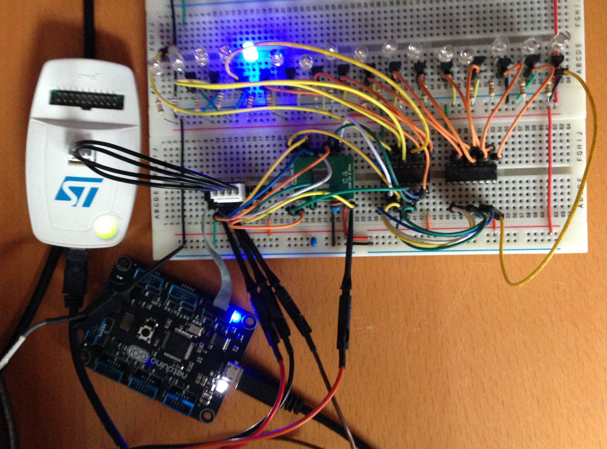
Output Expander Connected to Netdunio GO!
And here is a video of this working:
You can just see the Netduino Go! in the bottom left corner of the video.
Conclusion
At this point the basic concept has be proven and the application can perform the following:
- STM8S code can control one or more LEDs
- STM8S can be controlled using SPI
- Netduino Go! can pass instructions to the STM8S
One thing that did become apparent during this part of the process was that both the STM8S code and the Netduino code can be improved by improved grouping the functionality. For instance, in order to add the methods to the function table in the STM8S code I had to jump around the source code a little.
The next step in the process is to look at the hardware and start to prepare for prototype PCB manufacture.
Tags: Electronics, LED, Netduino, Software Development, STM8, The Way of the Register
Friday, April 12th, 2013 at 10:52 am • Electronics, Netduino, Software Development, STM8 • RSS 2.0 feed Both comments and pings are currently closed.