Windows Application Communicating with Netduino Over USB
May 28th, 2011 • Netduino, Software Development • Comments Off on Windows Application Communicating with Netduino Over USBWhilst the Netduino Plus has the advantage of being able to communicate with a PC by networking, the Netduino and the Netduino Mini do not have this capability built in. The simplest way of communicating with these two devices is probably by a serial connection. Both of these devices differ in the capabilities, one has two TTL COM ports whilst the other (the Netduino Mini) has a RS232 COM port and a TTL COM port.
This article discusses the connection using the TTL COM port to a PC using a USB connection. This is applicable to the Netduino, the Netduino Plus and the Netduino Mini.
USB Connection
Before we can start to write any software we need to make the physical connection. There are a few options available, a breakout board which converts the USB connection into a serial connection or a cable which has the conversion hardware built in. I went for the later option as this seemed simpler. The cable I purchased was the FTDI 5V VCC 3.3V IO cable. Plugging this cable into the PC installed new drivers (on Windows 7) and created a new COM port for me.
Connecting the cable was simple, The ground on the cable connected to the ground on the Netduino. The Tx and Rx connections needed to be crossed. So Rx on the cable went to the Netduino digital pin 1 and Tx on the cable connected to Netduino digital pin 0.
Software
This solution requires two projects, a Windows Forms application and a Netduino application.
Windows Form Application
This application will simply send commands in the form of lines of text down the serial port to the Netduino. Each command will terminate with a r character. This application is simple and mimics sending a command to turn an LED on or off.The application looks like this:
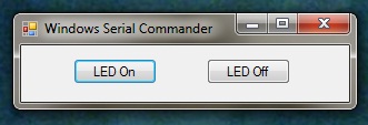
Windows Serial Interface
Clicking the LED On button sends the string LED=1 down the serial line to the listening device. Similarly, clicking on LED Off button sends the command LED=0 to the device.
The code to achieve this is trivial and there are only three parts, the first is to create the connection (see MainForm_Load) and the second and third parts send the command to the device (see btnLEDOn_Click and btnLEDOff_Click).
/// <summary>
/// Initialise the application.
/// </summary>
private void MainForm_Load(object sender, EventArgs e)
{
	com6 = new SerialPort("COM6", 9600, Parity.None, 8, StopBits.One);
	com6.Open();
}

/// <summary>
/// Send a command to the device listening on the com port.
/// </summary>
private void btnLEDOn_Click(object sender, EventArgs e)
{
	com6.Write("LED=1\r");
}

/// <summary>
/// Send a command to turn the LED off.
/// </summary>
private void btnLEDOff_Click(object sender, EventArgs e)
{
	com6.Write("LED=0\r");
}
Netduino Application
The Netduino application is a little more complex as it has to listen to the serial port and assemble a buffer containing the commands being received. The achieve this I abstracted the serial port processing into a separate class. This class took care of listening to the serial port and building up a beffer. The class then provided a way of reading a line of text from the buffer and presenting this to the caller as a single entity. The main code for this is contained in the class CommPort and can be found in the SerialComms.cs file in the attached project.
The main program loop becomes a simple affair and looks like this:
public static void Main()
{
    CommPort port = new CommPort(SerialPorts.COM1, BaudRate.Baudrate9600, Parity.None, 8, StopBits.One);
    while (true)
    {
        string text = port.ReadLine();
        if (text.Length != 0)
        {
            Debug.Print("Command: " + text);
        }
        Thread.Sleep(1000);
    }
}
To run the code I compiled the Windows Form application and then navigated (using Windows explorer) to the directory containing the executable. Double clicking on this started the application and opened the COM port. Next I deployed the Netduino application to the Netduino and with the debugger attched I clicked on the LED On button in the Windows application. A short time later the text Command: LED=1 appeared in the debug window.
The code for this project can be found here (WinFormSerialExample.zip).