20×4 LCD Display and NuttX
Time for some more experimentation with NuttX, today serial LCDs.
Serial LCDs
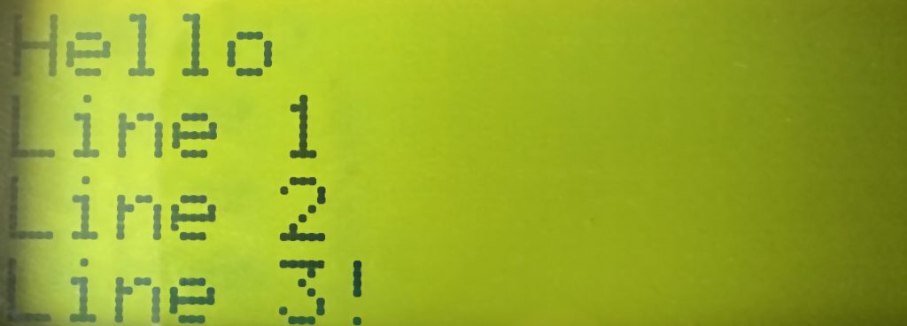
Small LCD displays can be found in many scientific instruments as they provide a simple way to display a small amount of information to the user. Typically these displays are 16×2 (2 lines of 16 characters) or 20×4 (4 lines of 20 characters) displays. The header to this article shows part of the output from a 20×4 display.
Communication with these displays is normally through a 4 or 8 bit interface when talking directly to the controller chip for the LCD. Using 4 or 8 data lines for communication with the LCD is a large burden on a small microcontroller. To overcome this, several vendors have produced a backpack that can be attached to the display. The backpack uses a smaller number of microcontroller lines for communication while still being able to talk to the LCD controller chip.
This post looks at using such and LCD and backpack with NuttX running on the Raspberry Pi Pico W.
NuttX Channel (Youtube)
A great place to start with NuttX is to have a look at the NuttX Channel on Youtube as there are a number of quick getting started tutorials covering a number of subject. In fact there is one covering a 16×2 LCD display which is similar to what will be used in this tutorial, with a small difference.
The video linked above covers a lot of what is needed to get 16×2 LCD up and running. There are some small changes that are needed as NuttX has moved on since the video was released.
Hardware
The major changes compared to the video above are:
- Microcontroller used will be the Raspberry Pi Pico W
- LCD display will be 20×4 display
The LCD display used here will be a larger physical display (20×4 instead of 16×2) but it will still use the same interface on the backpack, namely the PCF8574 GPIO expander. This uses I2C as a communication protocol so reduces the number of GPIO lines required from 8 to 2.
There are two I2C busses on the Pico W, I2C0 and I2C1 and in this case I2C1 will be the chosen interface. Something that caused some issues but more on that later.
For now we start with a base configuration with the LCd connected to GPIO6 and GPIO7 on the Pico W.
Configuring NuttX
Configuration followed much of the video linked above enabling the following:
- Enable I2C master and I2c1 in the System Type menu
- I2C Driver Support in the Device Drivers menu
- PCF8574 support through Device Drivers, Alphanumeric Drivers menus
- Segment LCD CODEC in the Library Routines menu
- Segment LCD Test in the Application Configuration, Examples menu
Time to build, deploy and run.
- make clean followed by make -j built the system
- The application was then deployed to the Pico W and board was reset
- The application can be run by connecting a terminal/serial application to the board an running the command slcd
Nothing appears on the display. Time to check the connections and break out the debugger.
Troubleshooting
Checking the connections showed that everything looked to be in order. The display was showing a faint pixel pattern which is typical of these displayed when they have been powered correctly but there is no communication. Double checking the I2C connections showed everything in theory was good.
Over to the software. Running through the configuration again and all looks good here. So lets try I2C0 instead of I2C1, quick change of the configuration in the software and moving some cables around and it works!
So lets go back to the I2C1 configuration, recompile and deploy to the board and it works. What!
It turns out that I had not moved the connections from I2C0 back to I2C1.
The default application was also only displaying 1 line of text. So let’s expand this to display 4 lines of text, namely:
- Hello
- Line1
- Line2
- Line3
Running the application gives only two line of text:
- Hello
- Line3
How odd.
Lets Read the Sources
After a few hours of tracing through the sources we find ourselves looking in the file rp2040_common_bringup.c where there is this block of code:
#ifdef CONFIG_LCD_BACKPACK
    /* slcd:0, i2c:0, rows=2, cols=16 */

    ret = board_lcd_backpack_init(0, 0, 2, 16);
    if (ret < 0)
    {
        syslog(LOG_ERR, "Failed to initialize PCF8574 LCD, error %d\n", ret);
        return ret;
        return ret;
    }
#endif
This suggests that the serial LCD test example is always configured to use a 16×2 LCD display on I2C0. This explains why we saw only two lines of output on the display and also why the code did not work on I2C1.
Changing ret = board_lcd_backpack_init(0, 0, 2, 16); to ret = board_lcd_backpack_init(0, 1, 4, 20); and recompiling generated the output we see at the top of this post.
Navigating to the System Type menu also allowed the I2C1 pins to be changed to 26 and 27 and the system continued to generate the expected results.
Conclusion
This piece of work took a little more time than expected and it would have been nice to have had the options within the configuration system to change the display and I2C parameters. As it stands at the moment using a 20×4 display requires changes to the OS source code. This is a trivial change but it does make merging / rebasing with later versions of the system a little more problematic.
Tags: Electronics, NuttX, Pico, Software Development
Sunday, July 23rd, 2023 at 4:30 pm • Electronics, NuttX, Pico, Software Development • RSS 2.0 feed Both comments and pings are currently closed.
