Design the System
Friday, April 14th, 2017One of the current projects on the go is a level shifter for the Teensy 3.6 using the TXS0108E chip. The aim is to allow the use of as many of the Teensy’s GPIO pins as possible to allow the development of another project that is working on 5V logic levels.
This project reminded me that when putting together a microcontroller project that the system is made up of both hardware and software. Sometimes a design decision made in one element can have an adverse effect on the other.
Design Decisions
From the start it was decided that the GPIO pins would have a one to one mapping from the microcontroller to the external bus. So pin 1 on the microcontroller would map to pin 1 on the external connectors.
This would make coding easy when using the Arduino API. So connecting to the external bus and outputting a digital high signal on pin 1 would become:
pinMode(1, OUTPUT);
digitalWrite(1, HIGH);
Impact
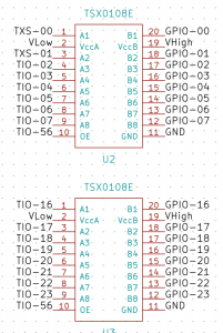
Putting the circuit together in KiCAD resulted in the following design:
As you can see, the Teensy GPIOS (TIO-1…) mapped directly to the external bus (GPIO-1…)
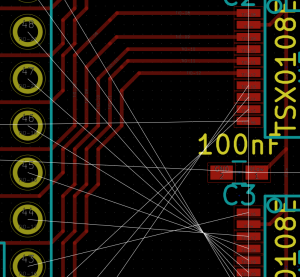
When translated into the rats nest there were three occurrences of the following:
Routing this was going to be a nightmare.
Changing the Design
At this point the penny dropped that a small change in the software would make the routing a whole lot easier.
Instead of using the pin numbers directly, a #define could be used for the external bus pin numbers. The above snippet would become:
#define BUS_IO1    30
.
.
.
pinMode(BUS_IO1, OUTPUT);
digitalWrite(BUS_IO1, HIGH);
This small change to the design created a one off task to create a header file for the board but it made the routing a lot easier.
Conclusion
Sometimes a small change may create a new task (creating the header file) but may possibly save more time elsewhere in the project.
Moral of the story, Design the system as a whole, not the individual components.


