STM8S I2C Master Devices
I have finally managed to dig out the TMP102 temperature sensor from the back of the electronic breakout board cupboard. Why am I interested in this sensor, well it is about the only I2C device I actually own and I2C is one of the few areas I have not really looked at on the STM8S.
This article will explore the basics of creating a I2C master device using the STM8S as the bus master and the TMP102 as the slave device.
I2C Protocol
I2C (Inter-Integrated Circuit) is a communication protocol allowing bi-directional communication between two or more devices over two wires. The protocol allows a device to be in one of four modes:
- Master transmit
- Master receive
- Slave transmit
- Slave receive
The Wikipedia article contains a good description of the protocol and the various modes and the bus characteristics.
For the purposes of this post the STM8S will need to be in master mode as it will be controlling the communication flow with the temperature sensor which is essentially a dumb device.
Communicating with the TMP102
The TMP102 is a simple device which returns two bytes of data which represent the current reading from a temperature sensor. The process for reading the temperature is as follows:
- Master device transmits the slave address on the SDA line along with a bit indicating that it wishes to read data from the slave device
- Master device enters Master Receive mode
- Slave device transmits two bytes of data representing the temperature
- Master device closes down the communication sequence
The temperature can be calculated according to the following formula:
Temperature in centigrade = (((byte0 * 256) + byte1) / 16) * 0.0625
Wiring up the TMP102
The sensor breakout I have has 6 connections of which we will connect five:
| Sensor Breakout Pin | Connected to |
| SDA | Microcontroller SDA line |
| SCK | Microcontroller SCK |
| Vcc | 3.3 V |
| GND | Ground |
| ADR0 | Ground |
This should result in the breakout having an I2C address of 0x48.
Netduino Code
The Netduino 3 runs the .NET Microframework (NETMF). This has built in class for communicating over I2C. A simple application will give a reference point for how the protocol should work.
using Microsoft.SPOT;
using Microsoft.SPOT.Hardware;
using System.Threading;

namespace TMP102
{
    public class Program
    {
        public static void Main()
        {
            //
            //  Create a new I2C device for the TMP102 on address 0x48 with the clock
            //  running at 50 KHz.
            //
            I2CDevice tmp102 = new I2CDevice(new I2CDevice.Configuration(0x48, 50));
            //
            //  Create a transaction to read two bytes of data from the TMP102 sensor.
            //
            byte[] buffer = new byte[2];
            I2CDevice.I2CTransaction[] reading = new I2CDevice.I2CTransaction[1];
            reading[0] = I2CDevice.CreateReadTransaction(buffer);
            while (true)
            {
                //
                //  Read the temperature.
                //
                int bytesRead = tmp102.Execute(reading, 100);
                //
                //  Convert the reading into Centigrade and Fahrenheit.
                //
                int sensorReading = ((buffer[0] << 8) | buffer[1]) >> 4;
                double centigrade = sensorReading * 0.0625;
                double fahrenheit = centigrade * 1.8 + 32;
                //
                //  Display the readings in the debug window and pause before repeating.
                //
                Debug.Print(centigrade.ToString() + " C / " + fahrenheit.ToString() + " F");
                Thread.Sleep(1000);
            }
        }
    }
}
Running this on the Netduino gives the following output in the debug window:
20.6875 C / 69.237500000000011 F
20.625 C / 69.125 F
20.6875 C / 69.237500000000011 F
20.6875 C / 69.237500000000011 F
20.625 C / 69.125 F
20.6875 C / 69.237500000000011 F
20.625 C / 69.125 F
20.625 C / 69.125 F
20.625 C / 69.125 F
20.625 C / 69.125 F
20.625 C / 69.125 F
Hooking up the Saleae Logic 16 gives the following output for a single reading:
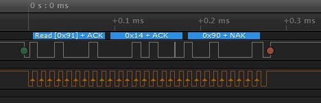
I2C communication with a TMP102 and a Netduino 3
STM8S Implementation
The NETMF class used above hides a lot of the low level work which the STM8S will have to manage. In order to communicate with the TMP102 the STM8S will have to perform the following:
- Enter master transmit mode
- Send the 7-bit address of the sensor
- Send a single bit indicating that we want to read from the sensor
- Wait for the slave to respond with an ACK
- Enter master receiver mode
- Read the bytes from the slave device. Send an ACK signal for all bytes except the last one.
- Send a NAK signal at the end of the sequence
The first task is to initialise the I2C system on the STM8S:
//
//  Initialise the I2C system.
//
void InitialiseI2C()
{
    I2C_CR1_PE = 0;                     //  Diable I2C before configuration starts.
    //
    //  Setup the clock information.
    //
    I2C_FREQR = 16;                     //  Set the internal clock frequency (MHz).
    I2C_CCRH_F_S = 0;                   //  I2C running is standard mode.
    I2C_CCRL = 0xa0;                    //  SCL clock speed is 50 KHz.
    I2C_CCRH_CCR = 0x00;
    //
    //  Set the address of this device.
    //
    I2C_OARH_ADDMODE = 0;               //  7 bit address mode.
    I2C_OARH_ADDCONF = 1;               //  Docs say this must always be 1.
    //
    //  Setup the bus characteristics.
    //
    I2C_TRISER = 17;
    //
    //  Turn on the interrupts.
    //
    I2C_ITR_ITBUFEN = 1;                //  Buffer interrupt enabled.
    I2C_ITR_ITEVTEN = 1;                //  Event interrupt enabled.
    I2C_ITR_ITERREN = 1;
    //
    //  Configuration complete so turn the peripheral on.
    //
    I2C_CR1_PE = 1;
    //
    //  Enter master mode.
    //
    I2C_CR2_ACK = 1;
    I2C_CR2_START = 1;
}
Some of the initialisation for the I2C bus needs to be performed whilst the peripheral is disabled, notably the setup of the clock speed. The method above diables the I2C bus, sets up the clock and addressing mode, turns on the interrupts for the peripheral and then enables the I2C bus. Finally, the method sets up the system to transmit ACKs following data reception and then sends the Start bit.
The communication with the slave device is handled by an Interrupt Service Routine (ISR). The initialisation method above will have taken control of the bus and set the start condition. An interrupt will be generated once the start condition has been set.
The master then needs to send the 7-bit address followed by a 1 to indicate the intention to read data from the bus. These two are normally combined into a single byte, the top 7-bits containing the device address and the lower bit indicating the mode (read – 1 or write – 0).
if (I2C_SR1_SB)
{
    //
    //  Master mode, send the address of the peripheral we
    //  are talking to.  Reading SR1 clears the start condition.
    //
    reg = I2C_SR1;
    //
    //  Send the slave address and the read bit.
    //
    I2C_DR = (DEVICE_ADDRESS << 1) | I2C_READ;
    //
    //  Clear the address registers.
    //
    I2C_OARL_ADD = 0;
    I2C_OARH_ADD = 0;
    return;
}
This above code checks the status registers to see if the interrupt has been generated because of a start condition. If it has then the STM8S is setup to send the address of the TMP102 along with the read bit.
Assuming that no error conditions are generated, the next interrupt generated will indicate that the address has been sent to the slave successfully. This condition is dealt with by reading two of the status registers and clearing the address registers:
if (I2C_SR1_ADDR)
{
    //
    //  In master mode, the address has been sent to the slave.
    //  Clear the status registers and wait for some data from the salve.
    //
    reg = I2C_SR1;
    reg = I2C_SR3;
    return;
}
At this point the address has been sent successfully and the I2C peripheral should be ready to start to receive data.
The I2C protocol requires that the data bytes are acknowledged by the master device with an ACK signal. All except for the last data byte, this must be acknowledged with a NAK signal. The I2C_CR2_ACK bit determines if an ACK or NAK is sent following each byte.
The master device can then continue to hold control of the bus or it can send a STOP signal indicating that the flow of communication has ended.
These two conditions are dealt with by resetting the I2C_CR2_ACK bit and setting the I2C_CR2_STOP bit.
The fulll ISR for the I2C bus looks like this:
//
//  I2C interrupts all share the same handler.
//
#pragma vector = I2C_RXNE_vector
__interrupt void I2C_IRQHandler()
{
    if (I2C_SR1_SB)
    {
        //
        //  Master mode, send the address of the peripheral we
        //  are talking to.  Reading SR1 clears the start condition.
        //
        reg = I2C_SR1;
        //
        //  Send the slave address and the read bit.
        //
        I2C_DR = (DEVICE_ADDRESS << 1) | I2C_READ;
        //
        //  Clear the address registers.
        //
        I2C_OARL_ADD = 0;
        I2C_OARH_ADD = 0;
        return;
    }
    if (I2C_SR1_ADDR)
    {
        //
        //  In master mode, the address has been sent to the slave.
        //  Clear the status registers and wait for some data from the salve.
        //
        reg = I2C_SR1;
        reg = I2C_SR3;
        return;
    }
    if (I2C_SR1_RXNE)
    {
        //
        //  The TMP102 temperature sensor returns two bytes of data
        //
        _buffer[_nextByte++] = I2C_DR;
        if (_nextByte == 1)
        {
            I2C_CR2_ACK = 0;
            I2C_CR2_STOP = 1;
        }
        return;
    }
}
Running the Application
The application needs to be rounded out a little in order to read and store the two data bytes in a buffer. Some diagnostics can also be provided by setting one of the ports on the STM8S to output and bit banging the data ready through this port. Add to this some initialisation code and the full application looks as follows:
//
//  This application demonstrates the principles behind developing an
//  I2C master device on the STM8S microcontroller.  The application
//  will read the temperature from a TMP102 I2C sensor.
//
//  This software is provided under the CC BY-SA 3.0 licence.  A
//  copy of this licence can be found at:
//
//  http://creativecommons.org/licenses/by-sa/3.0/legalcode
//
#if defined DISCOVERY
    #include <iostm8S105c6.h>
#else
    #include <iostm8s103f3.h>
#endif
#include <intrinsics.h>

//
//  Define some pins to output diagnostic data.
//
#define PIN_BIT_BANG_DATA       PD_ODR_ODR4
#define PIN_BIT_BANG_CLOCK      PD_ODR_ODR5
#define PIN_ERROR               PD_ODR_ODR6

//
//  I2C device related constants.
//
#define DEVICE_ADDRESS          0x48
#define I2C_READ                1
#define I2C_WRITE               0

//
//  Buffer to hold the I2C data.
//
unsigned char _buffer[2];
int _nextByte = 0;

//
//  Bit bang data on the diagnostic pins.
//
void BitBang(unsigned char byte)
{
    for (short bit = 7; bit >= 0; bit--)
    {
        if (byte & (1 << bit))
        {
            PIN_BIT_BANG_DATA = 1;
        }
        else
        {
            PIN_BIT_BANG_DATA = 0;
        }
        PIN_BIT_BANG_CLOCK = 1;
        __no_operation();
        PIN_BIT_BANG_CLOCK = 0;
    }
    PIN_BIT_BANG_DATA = 0;
}

//
//  Set up the system clock to run at 16MHz using the internal oscillator.
//
void InitialiseSystemClock()
{
    CLK_ICKR = 0;                       //  Reset the Internal Clock Register.
    CLK_ICKR_HSIEN = 1;                 //  Enable the HSI.
    CLK_ECKR = 0;                       //  Disable the external clock.
    while (CLK_ICKR_HSIRDY == 0);       //  Wait for the HSI to be ready for use.
    CLK_CKDIVR = 0;                     //  Ensure the clocks are running at full speed.
    CLK_PCKENR1 = 0xff;                 //  Enable all peripheral clocks.
    CLK_PCKENR2 = 0xff;                 //  Ditto.
    CLK_CCOR = 0;                       //  Turn off CCO.
    CLK_HSITRIMR = 0;                   //  Turn off any HSIU trimming.
    CLK_SWIMCCR = 0;                    //  Set SWIM to run at clock / 2.
    CLK_SWR = 0xe1;                     //  Use HSI as the clock source.
    CLK_SWCR = 0;                       //  Reset the clock switch control register.
    CLK_SWCR_SWEN = 1;                  //  Enable switching.
    while (CLK_SWCR_SWBSY != 0);        //  Pause while the clock switch is busy.
}

//
//  Initialise the I2C system.
//
void InitialiseI2C()
{
    I2C_CR1_PE = 0;                     //  Diable I2C before configuration starts.
    //
    //  Setup the clock information.
    //
    I2C_FREQR = 16;                     //  Set the internal clock frequency (MHz).
    I2C_CCRH_F_S = 0;                   //  I2C running is standard mode.
    I2C_CCRL = 0xa0;                    //  SCL clock speed is 50 KHz.
    I2C_CCRH_CCR = 0x00;
    //
    //  Set the address of this device.
    //
    I2C_OARH_ADDMODE = 0;               //  7 bit address mode.
    I2C_OARH_ADDCONF = 1;               //  Docs say this must always be 1.
    //
    //  Setup the bus characteristics.
    //
    I2C_TRISER = 17;
    //
    //  Turn on the interrupts.
    //
    I2C_ITR_ITBUFEN = 1;                //  Buffer interrupt enabled.
    I2C_ITR_ITEVTEN = 1;                //  Event interrupt enabled.
    I2C_ITR_ITERREN = 1;
    //
    //  Configuration complete so turn the peripheral on.
    //
    I2C_CR1_PE = 1;
    //
    //  Enter master mode.
    //
    I2C_CR2_ACK = 1;
    I2C_CR2_START = 1;
}

//
//  I2C interrupts all share the same handler.
//
#pragma vector = I2C_RXNE_vector
__interrupt void I2C_IRQHandler()
{
    if (I2C_SR1_SB)
    {
        //
        //  Master mode, send the address of the peripheral we
        //  are talking to.  Reading SR1 clears the start condition.
        //
        reg = I2C_SR1;
        //
        //  Send the slave address and the read bit.
        //
        I2C_DR = (DEVICE_ADDRESS << 1) | I2C_READ;
        //
        //  Clear the address registers.
        //
        I2C_OARL_ADD = 0;
        I2C_OARH_ADD = 0;
        return;
    }
    if (I2C_SR1_ADDR)
    {
        //
        //  In master mode, the address has been sent to the slave.
        //  Clear the status registers and wait for some data from the salve.
        //
        reg = I2C_SR1;
        reg = I2C_SR3;
        return;
    }
    if (I2C_SR1_RXNE)
    {
        //
        //  The TMP102 temperature sensor returns two bytes of data
        //
        _buffer[_nextByte++] = I2C_DR;
        if (_nextByte == 1)
        {
            I2C_CR2_ACK = 0;
            I2C_CR2_STOP = 1;
        }
        else
        {
            BitBang(_buffer[0]);
            BitBang(_buffer[1]);
        }
        return;
    }
    //
    //  If we get here then we have an error so clear
    //  the error and continue.
    //
    unsigned char reg = I2C_SR1;
    reg = I2C_SR3;
    //
    //  Send a diagnostic signal to indicate we have cleared
    //  the error condition.
    //
    PIN_ERROR = 1;
    __no_operation();
    PIN_ERROR = 0;
}

//
//  Main program loop.
//
int main()
{
    __disable_interrupt();
    //
    //  Initialise Port D.
    //
    PD_ODR = 0;             //  All pins are turned off.
    PD_DDR_DDR4 = 1;        //  Port D, bit 4 is output.
    PD_CR1_C14 = 1;         //  Pin is set to Push-Pull mode.
    PD_CR2_C24 = 1;         //  Pin can run up to 10 MHz.
    //
    PD_DDR_DDR5 = 1;        //  Port D, bit 5 is output.
    PD_CR1_C15 = 1;         //  Pin is set to Push-Pull mode.
    PD_CR2_C25 = 1;         //  Pin can run up to 10 MHz.
    //
    PD_DDR_DDR6 = 1;        //  Port D, bit 6 is output.
    PD_CR1_C16 = 1;         //  Pin is set to Push-Pull mode.
    PD_CR2_C26 = 1;         //  Pin can run up to 10 MHz.
    //
    InitialiseSystemClock();
    InitialiseI2C();
    __enable_interrupt();
    while (1)
    {
        __wait_for_interrupt();
    }
}
Putting this in a project and running on the STM8S gives the following output on the Saleae logic analyser:
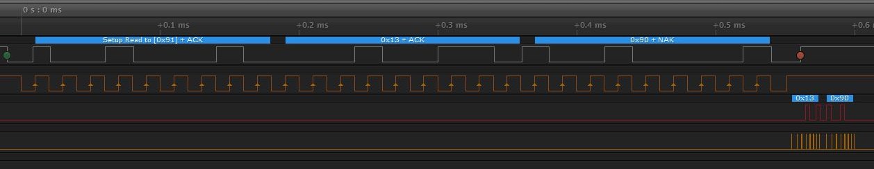
I2C Communication between STM8S and a TMP102
The output looks similar to that from the Netduino application above. Breaking out the calculator and using the readings in the above screen shot gives a temperature of 19.6 C which is right according to the thermometer in the room.
Conclusion
The above application shows the basics of a master I2C application. The code needs to be expanded to add some error handling to detect some of the errors that can occur (bus busy, acknowledge failures etc.) but the basics are there.
On to STM8S slave devices…

[…] succeeded at getting a basic I2C master working on the STM8S it is not time to start to look at I2C slave devices on the […]