OpenIR Interrupts
A few nights ago I was working on implementing the processing the command sequences stored in the STM8S into IR pulses. The Win32 configuration application takes a series of high / low transitions measured in microseconds and turns the infra-red LED on and off accordingly. Doing this would require a signal capable of being triggered to the nearest microsecond.
This is where the plot fell apart.
Looking at the application now I think it is a case of over engineering the problem. By modifying the design parameters to be more realistic the problem can be overcome.
How Fast Do We Need To Be?
Previous articles have shown how a 2-3 MHz pulse can be generated by setting the system clock to 16MHz and toggling a port in a while loop. It has also been shown how Timer 2 can be used to generate a square wave using an interrupt based upon the clock pulse. The challenge is to generate and interrupt at a high enough frequency.
From the start it was recognised that the generation of a 1 MHz signal was ambitious using interrupts. Raising an interrupt on the STM8S takes 9 clock cycles and working on a 16MHz clock this only leaves 5 clock cycles for the work of the Interrupt SubRoutine (ISR) before the microcontroller returns to sleep and the whole cycle restarts.
So the question becomes, is this a problem?
Breaking out the calculator reveals that a 38KHz signal (a common frequency used for infra-red signals) has a period of 26 microseconds. So if we were to send a single pulse the ISR would have to respond within 26 microseconds. Having a carrier signal would not make sense if there were less than two carrier signal pulses within the infra-red signal. This would result in a minimum frequency of 19KHz which is well within the capabilities of the STM8S.
As I said, over engineering, or more likely, worrying about a problem which does not really exist.
Recreating the Nikon Shutter Trigger Signal
The changes which have been made are all aimed at making the remote control a universal remote control. It is i=now time to get back to the orignal aims of the project, namely to be able to trigger a Nikon camera.
The last post demonstrated the ability to create a configurable sequences of pulses / pauses and store these in the EEPROM. The next step is to convert these into a pulse sequence based upon a 38KHz carrier signal.
Although the predominant carrier frequency for an infra-red remote control is 38KHz, this implementation allows for the carrier frequency to be configured. In order to do this the software will need to change the counter and prescalar values of Timer 1, Channel 4. Four bytes of the EEPROM are reserved for these two values. The Windows application performs most of the work by calculating the required values:
int count = 0;
int prescalar = 0;
bool error = false;

if (value < 1)
{
    error = true;
}
else
{
    count = (int) (CLOCK_FREQUENCY / value);
    while ((prescalar < 65536) && (count > 65535))
    {
        prescalar++;
        count = (int) (CLOCK_FREQUENCY / (value * prescalar));
    }
    error = (prescalar == 65536);
}

if (error)
{
    float maxFrequency = CLOCK_FREQUENCY / 65535;
    throw new ArgumentOutOfRangeException("CarrierFrequency", string.Format("Carrier frequency should be between 1 and {0} Hz.", maxFrequency));
}
else
{
    _memory[PULSE_DURATION_OFFSET] = (byte) (count >> 8);
    _memory[PULSE_DURATION_OFFSET + 1] = (byte) (count & 0xff);
    _memory[PRESCALAR_OFFSET] = (byte) (prescalar >> 8);
    _memory[PRESCALAR_OFFSET + 1] = (byte) (prescalar & 0xff);
}
value is the desired frequency in Hz. The code cycles through the possible prescalar values until the right combination of counter and prescalar vales are obtained. The prescalar for Timer 1 is a value between 0 and 65535. One thing to note is that the value of the counter and the prescalar may not always return an exact frequency, for example, a carrier signal of 38KHz results in counter and prescalar values which generate a 38,004Hz signal. Not exact but given that the remote is using the internal oscillator we cannot expect an exact output anyway.
The perfectionist in me finds this to be disturbing but it is something I’ll have to live with.
Back on the remote control the application needs to use the configuration information in the EEPROM in order to regenerate the carrier signal for the remote control.
//
//  Set up Timer 1, channel 4 to output a PWM signal (the carrier signal).
//
void SetupTimer1()
{
    TIM1_ARRH = *((unsigned char *) EEPROM_PULSE_DURATION);
    TIM1_ARRL = *((unsigned char *) (EEPROM_PULSE_DURATION + 1));
    TIM1_PSCRH = *((unsigned char *) EEPROM_PRESCALAR_OFFSET);
    TIM1_PSCRL = *((unsigned char *) (EEPROM_PRESCALAR_OFFSET + 1));
    //
    //  Now configure Timer 1, channel 4.
    //
    TIM1_CCMR4_OC4M = 7;    //  Set up to use PWM mode 2.
    TIM1_CCER2_CC4E = 1;    //  Output is enabled.
    TIM1_CCER2_CC4P = 0;    //  Active is defined as high.
    //
    //  Work out the 50% duty cycle based upon the count.
    //
    unsigned short fiftyPercentDutyCycle;
    fiftyPercentDutyCycle = *((unsigned char *) EEPROM_PULSE_DURATION);
    fiftyPercentDutyCycle <<= 8;
    fiftyPercentDutyCycle += *((unsigned char *) (EEPROM_PULSE_DURATION + 1));
    fiftyPercentDutyCycle >>= 1;
    TIM1_CCR4H = ((fiftyPercentDutyCycle >> 8) & 0xff);
    TIM1_CCR4L = fiftyPercentDutyCycle & 0xff;
    //
    TIM1_BKR_MOE = 0;       //  Disable the main output.
    TIM1_CR1_CEN = 1;       //  Enable the timer.
}
Much of this code uses the counter values from the EEPROM to set up the PWM on Timer 1 Channel 4.
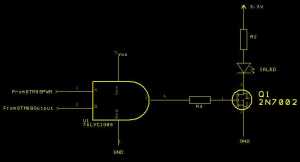
Two changes which have been made which do not impact the frequency of the carrier signal are the last two lines of the method. Previous versions of the code turned the time output on and the timer off. Here the Timer is turned on and the output off. This has been done to remove the need for the AND gate in the LED driver section of the circuit:
The AND gate takes the PWM signal from the STM8S along with an output enable signal (Port D, pin 3) from the STM8S. Changing the code to disable the timer removes the need for the output enable signal. The timer output is set to active high and when the timer is disabled the output pin of the timer goes into a high state. This problem is resolved by leaving the timer active and disabling the main output of the timer.
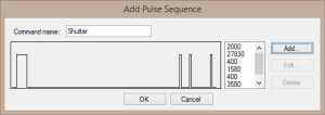
Another small change is to Timer 2, the timer used to determine the duration of the output of the carrier frequency. The Windows application takes the output and pause periods in microseconds. The Nikon shutter signal looks like this:
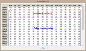
When this is encoded in the EEPROM the sequence data looks as follows:
The memory is encoded as follows:
| Memory Offset | Length | Description |
| 0x00 | 0x10 | Name of the remote control. |
| 0x10 | 0x02 | Timer 1 counter value for the carrier signal. |
| 0x12 | 0x02 | Timer 1 prescalar for the carrier signal. |
| 0x14 | 0x01 | Number of pulse sequences / commands in the EEPROM. |
| 0x20 | 0x40 | Length of the sequences / commands in the sequence table. |
| 0x60 | 0x1f8 | Sequence / command data. |
Each of the commands is encoded as follows:
| Memory Offset | Length | Description |
| 0x00 | 0x08 | Name of the command. |
| 0x08 | 1 | Number of pulses / pauses in the command (n). |
| 0x09 | n * 2 | Command / pause duration in microseconds. |
Now let’s look at how this data can be retrieved and used.
Timer 2 can be configured with a clock prescalar in the range 1 to 32,768. With a clock frequency of 16MHz a prescalar of 16 would drop the clock frequency to 1MHz. Doing this makes the calculation of the counter values as simple as recording the number of microseconds in the 16-bit values used for the counters. The setup code for Timer 2 becomes:
//
//  Setup Timer 2 ready to process the pulse data.
//
void SetupTimer2()
{
    TIM2_PSCR = 4;
    TIM2_ARRH = 0;
    TIM2_ARRL = 0;
    TIM2_EGR_UG = 1;
    TIM2_IER_UIE = 1;       //  Enable the update interrupts.
}
The Timer 2 interrupt handler currently looks are follows:
//
//  Timer 2 Overflow handler.
//
#pragma vector = TIM2_OVR_UIF_vector
__interrupt void TIM2_UPD_OVF_IRQHandler(void)
{
    _currentPulse++;
    if (_currentPulse == _numberOfPulses)
    {
        //
        //  We have processed the pulse data so stop now.
        //
        PD_ODR_ODR3 = 0;
        TIM2_CR1_CEN = 0;
        TIM1_BKR_MOE = 0;
        _currentState = STATE_WAITING_FOR_USER;
    }
    else
    {
        TIM2_ARRH = *_pulseDataAddress++;
        TIM2_ARRL = *_pulseDataAddress++;
        TIM1_BKR_MOE = !TIM1_BKR_MOE;       //  Toggle the T1 output.
        TIM2_CR1_URS = 1;
        TIM2_EGR_UG = 1;
    }
    //
    //  Reset the interrupt otherwise it will fire again straight away.
    //
    TIM2_SR1_UIF = 0;
}
Where _pulseDataAddress points to the next pulse to be processed and _numberOfPulses holds the count of the number of pulses in this sequence.
The code below walks through the list of commands looking for the pulse data for the sequence number held in the command variable.
//
//  We have enough command data.  Now work out where the command is.
//
_pulseDataAddress = (unsigned char *) (EEPROM_SEQUENCE_DATA_OFFSET);
unsigned char *length = (unsigned char *) EEPROM_SEQUENCE_LENGTH_TABLE_OFFSET;
for (unsigned char index = 0; index < command; index++)
{
    _pulseDataAddress += *((unsigned char *) length);
}
Now we have the pulse sequence is is necessary to set up Timer 2 and the global variables pointing to the pulse data and the number of pulses.
//
//  Now start processing the pulse data for the specified command.
//
_currentState = STATE_RUNNING;
_pulseDataAddress += MAX_PULSE_NAME_LENGTH;     //  Skip the name.
_numberOfPulses = *_pulseDataAddress++;
_currentPulse = 0;
TIM2_ARRH = *_pulseDataAddress++;
TIM2_ARRL = *_pulseDataAddress++;
The final step is to turn on Timer 1 output and start Timer 2 running:
//
//  Now we have everything ready we need to force the Timer 2 counters to
//  reload and enable Timers 1 & 2.
//
TIM2_CR1_URS = 1;
TIM2_EGR_UG = 1;
TIM1_BKR_MOE = 1;
TIM2_CR1_CEN = 1;
Calling TransmitPulseData should allow the command sequence to be output. Adding the line of code TransmitPulseData(0); after the configuration code and hooking up the logic analyser results in the following output:
Conclusion
OpenIR has reached the point where command sequences can be edited and stored in the EEPROM and a single command sequence can be transmitted on a configurable carrier frequency.
Next steps:
- The pulse sequence storage in the Windows application still needs to be tidied up.
- When loading the EEPROM data the Windows application needs to regenerate the data for the list box containing the list of sequences.
- Add commands to send a determined sequence / command number.
- Redesign the board to remove the AND gate from the LED output.
Once the above has been completed additional connectivity options can be investigated.
For those who are interested, the source code for STM8S running the remote control is available for download.
Tags: Electronics, Software Development, STM8
Sunday, March 1st, 2015 at 10:06 am • Electronics, Software Development, STM8 • RSS 2.0 feed Both comments and pings are currently closed.


