MSP430 Launchpad
Shortly after it’s launch, I purchased a Texas Instruments MSP430 Launchpad board. It was about the time I had started to move away from the Netduino family of microcontrollers and started to look at alternatives to stretch myself a little more. I never managed to get the board talking to my laptop at the time and eventually gave up in frustration.
The last week I found the board and in possession of a new laptop and new OS I decided to give it one final go. A few downloads later (about 500MB to be precise) and I have it working!
MSP540 Launchpad
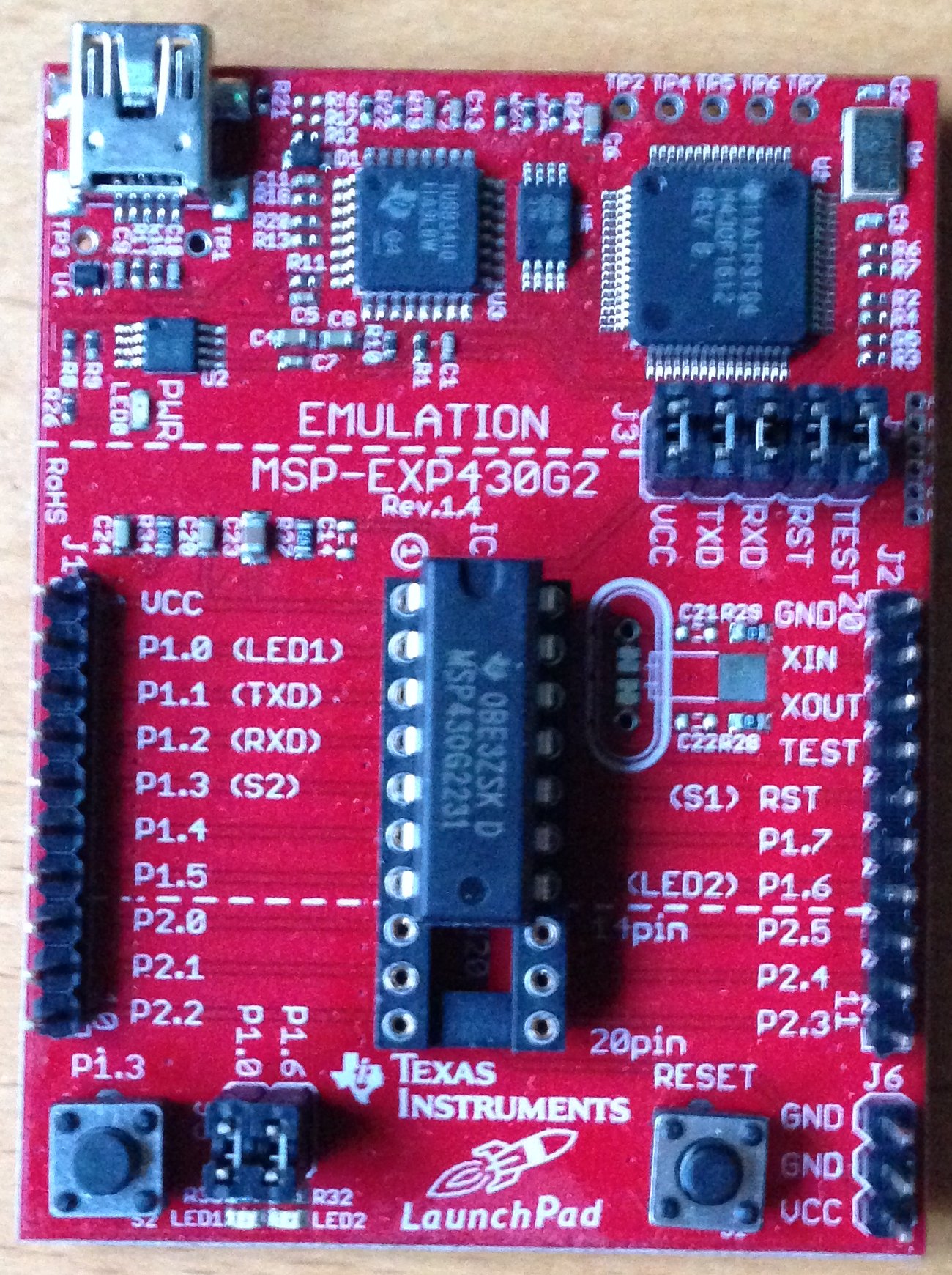
The MSP430 Launchpad (MSP430-EXP430G2) is a small development board for the MSP430 value line microcontrollers. The board is supplied with two variants of the MSP43 microcontroller, namely the MSP430G2231 and MSP430G2211 (both in DIP form).
I was attracted to this board for a few reasons:
- DIP packaging means that they can be used on breadboard (also available as SMD components)
- Cost. The microcontrollers themselves are available for as little as 50p in the UK
- Available in a wide variety of options (memory etc.)
- Free development tools
The board is not a large board and it contains very little circuitry apart from the integrated debugger.
MSP430 Launchpad
Only thing which remained was to see if I could get it working on my PC.
Development Tools
When it comes to developing for the MSP430 there are two options which I considered, the Texas Instruments Code Composer Studio and IAR systems Embedded Workbench.
Code Composer Studio is based on the popular Eclipse platform. The installation was quick and simple. The installer even asked if the add-ons for the MSP430 should be added into an existing Eclipse installation. This software does not appear to have any code restrictions.
The IAR installation is the same IAR Embedded Workbench which I have used in the past with the STM8S. The only difference is the addition of MSP430 support. The free Kickstarter edition of this software is limited to 4Kbytes of code for traditional MSP430 devices (8KBytes for MSP430X) and you are not allowed to use the system to develop commercial applications.
I have installed both of these tools as they both have their merits. I like the IAR compiler suite as I have one tool which I can use for the development of both MSP430 and STM8S applications. The code size limitation is unlikely to be an issue at the moment and as a hobbyist I am not intending to use the tool commercially.
Code Composer has the advantage that it has a little integration with Texas instruments web site and examples. For instance, the Resource explorer will allow you to easily access the MSP430 Wiki pages. These are really minor advantages as the examples are freely available and the Wiki web site is easily found. The main advantage with Code Composer is that there does not appear to be any restriction on use.
Other tools are also available and more information can be found on the Texas Instruments web site.
Hardware
The MSP430 Launchpad board is split into two areas. The upper quarter of the board contains the circuitry necessary to support programming chip and debugging the application deployed to the chip. The lower three quarters of the board are home to the 20 pin DIP socket for the MSP430, some headers, switches and LEDs. The headers will need to be added when you receive the board.
The switches and two LEDs are connected to the MSP430 by default and are great for the beginner as you can start to interact with the microcontroller immediately.
There is also space for an external oscillator should one be required.
Connecting the Board
This is where I ran into problems last time and sure enough it is where I ran into problems this time.
Having installed Code Composer I expected to have everything installed which was required to start using the MSP430 Launchpad board. So I fired up Code Composer, set up a new project using one of the Blinky LED examples, plugged in the board and prepared to hit the Debug button.
Plugging in the board gave me the usual message from Windows about a new USB device and the system set off looking for drivers. A minute or so later and I received the wonderful news that the driver could not be found.
Great! Say hello to Mr Google.
After a little searching I found some articles which indicated that the drivers needed updating (I’d already guessed that but always good to have it confirmed). A little more searching led me to the driver download page.
A quick installation later and the board was still not recognised. Try another USB port (getting desperate now). Driver installation window pops up and this time no error. Hitting the debug button in Code Composer deployed my Blinky sample application.
Interestingly, when I plugged the board into the original USB port it was recognised this time and I could deploy and debug from that port as well.
Generating a Pulse
Now I have a working environment it is time to write my own application. The first application I am going to attempt will generate a pulse using the internal watchdog. This is not a million miles away from the Blinky application in the samples. The main difference is that rather than use a loop to determine when the pulses are generated we will be using the in built watchdog.
I have chose to use IAR for this project as I am already familiar with the tool. Setting up a new project works the same way as using this platform for the STM8S. The only real difference is the need to change the device and debugger types.
First Step is to create and empty project:
- Create a new workspace (File->New Workspace)
- Create a new project (Project-%gt;Create New Project)
- Select the MSP430 tool chain and a C project with a main application
- Decide where you are going to put the application and give the project a name
You should now have a project with one file (main.c) with the following code:
#include "io430.h"

int main( void )
{
  // Stop watchdog timer to prevent time out reset
  WDTCTL = WDTPW + WDTHOLD;

  return 0;
}
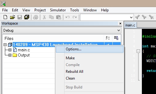
Next we need to set up the device and debugger types. The device I am using is the MSP430G2231. This is the default chip installed on the board when I purchased the Launchpad. Right click on the project name in the Workspace section of the Embedded Workbench IDE and select Options…
MSP430 Project Options
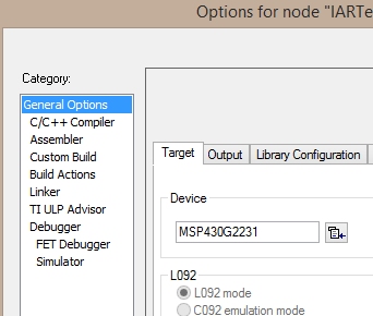
Set Device Type
Now change the debugger type (driver) from Simulator to FET Debugger:
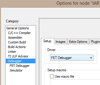
Set Debugger Type
Next, ensure that the connection is set to Texas Instruments USB-IF:

Set Debugger Connection Type
We are now ready to type in some code and test the connection. Press Ctrl-D in the IDE and the system should connect to the launchpad and deploy the application to the chip. The IDE will highlight the first line of code to be executed:
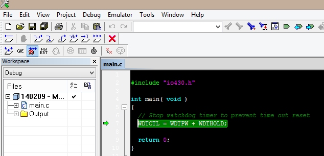
MSP430 Application Deployment Successful
We are now ready to write our first application.
#include "io430.h"

//
//  Watchdog timer ISR.
//
#pragma vector = WDT_VECTOR
__interrupt void WDT_ISR(void)
{
    //
    //  Clear the interrupt flag for watchdog timer.
    //
    IFG1 &= ~WDTIFG;
    //
    //  Toggle the output pin.
    //
    P1OUT = P1OUT ^ BIT7;
    //
    //  Go back to sleep.
    //
    __bis_SR_register_on_exit(LPM0_bits);
}

//
//  Main program loop.
//
int main( void )
{
    //
    //  Set the watchdog to 0.5ms trigger and enable the interrupt.
    //
    WDTCTL = WDT_MDLY_0_5;
    IE1 |= WDTIE;
    //
    //  Configure pin 7 on port 1 as an output pin.
    //
    P1DIR = BIT7;
    //
    //  Set pin 7 high.
    //
    P1OUT = BIT7;
    while   (1)
    {
        __bis_SR_register(LPM0_bits + GIE);
    }
}
Deploying this application to the chip and connecting up an oscilloscope to Port 1, Pin 7 gives the following trace:
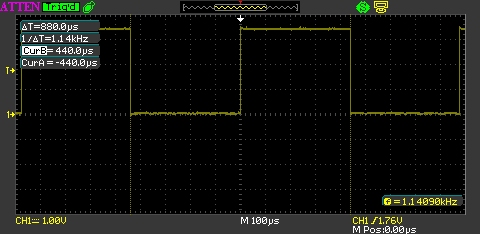
1.14KHz Pulse From MSP430
Success !
Conclusion
The availability of the MSP430 in DIP format makes it an interesting option for prototyping as you can easily breadboard your circuit. The STM8S which I have been using for a couple of years now can be breadboarded but only with the use of additional components.
The example above should have generated a 1KHz signal as the watchdog was configured to generate an interrupt every 0.5ms. In fact the frequency was a little higher as the interrupt was being generated every 440uS instead. This is not uncommon when using the internal oscillator in a microcontroller. The frequency could be made more accurate by using an external crystal but this would complicate the circuit. For most hobbyist purposes this is accurate enough.
Tags: Electronics, MSP430
Sunday, February 9th, 2014 at 9:57 am • Electronics, MSP430 • RSS 2.0 feed Both comments and pings are currently closed.
[…] the last post I was looking at the MSP430. The intention is to look at how it can be used for software debouncing […]
Very interesting article. The low power modes that the device supports could also make it very attractive for powering it from battery alone.
Thanks, glad you enjoyed it.
I thought it offered interesting possibilities as well. It maybe making a few more appearances in the future.