Modulated Nikon D70 Remote Control Signal
A quiet Sunday here in the North of England so I decided to add the 38.4KHz modulation to the Nikon D70 Infra-red Remote Control.
I considered two methods of modulating the signal:
- Software implementation using a timer
- Hardware implementation using PWM
The software implementation is attractive as it does not require the addition of any additional components to the circuit and hence reduces the cost of the remote control. On the downside, this requires a slightly more complex implementation and may cause some issues due to the timing of the interrupts.
Using PWM is a much simpler software solution as it only requires that the timers are setup correctly and turned on at the right time.
How Does Modulation Work?
Modulation works by combining a clock frequency (in the case of infra-red this is normally around 38KHz – 40 KHz) with a digital signal. When the digital signal is supposed to be at logic 1 then the clock signal is output rather than a stable logic level 1. When the signal is at logic level 0 then no signal is generated. The following illustrates this:
Digital signal:

Digital Signal
Clock signal:
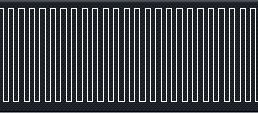
38.4KHz Clock Signal
Combined output:
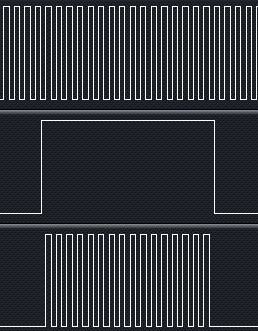
Digital Signal And Clock
In the final image above, the top trace shows the clock signal, the middle trace shows the digital signal we wish to generate and the lower trace shows the signal which should be output by the circuit.
Hardware Changes
The hardware solution requires the combination of a digital signal with a PWM signal. The easiest way to do this is to use a single AND gate taking input from the digital output required and a clock signal.
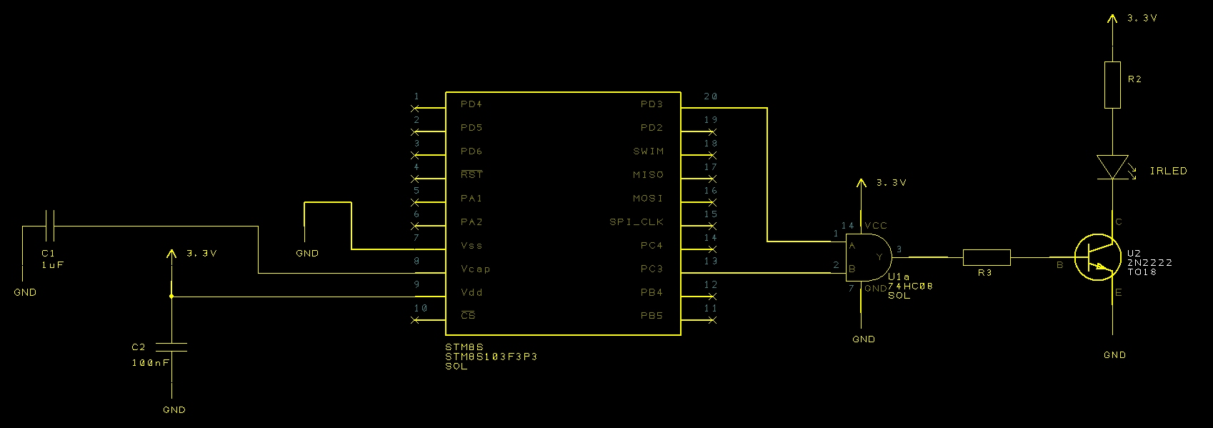
Nikon Remote Circuit With Added Modulation
Searching the RS Components web site lead to a single and gate component for a small price. This would be ideal for solving this problem.
Software Changes
The software changes are minimal as we simply need to configure a timer and turning it on and off as required. We will be using Timer 1, Channel 4 configured to generate a 38.4KHz PWM signal.
Setup
A 38.4KHz signal has a peak to peak duration of 26uS The system is running at 2MHz and so we would need a count value of 52 clock pulses (with no prescalar applied). Using Timer 2, Channel 4 results in the following setup code:
//--------------------------------------------------------------------------------
//
//  Set up Timer 1, channel 4 to output a single pulse lasting 240 uS.
//
void SetupTimer1()
{
    TIM1_ARRH = 0x00;       //  Reload counter = 51
    TIM1_ARRL = 0x33;
    TIM1_PSCRH = 0;         //  Prescalar = 0 (i.e. 1)
    TIM1_PSCRL = 0;
    //
    //  Now configure Timer 1, channel 4.
    //
    TIM1_CCMR4_OC4M = 7;    //  Set up to use PWM mode 2.
    TIM1_CCER2_CC4E = 1;    //  Output is enabled.
    TIM1_CCER2_CC4P = 0;    //  Active is defined as high.
    TIM1_CCR4H = 0x00;      //  26 = 50% duty cycle (based on TIM1_ARR).
    TIM1_CCR4L = 0x1a;
    TIM1_BKR_MOE = 1;       //  Enable the main output.
}
Timer 2 Interrupt Handler
A minor change to the Timer 2 interrupt handler is required to turn off Timer 1 when the signal is no longer being generated:
//--------------------------------------------------------------------------------
//
//  Timer 2 Overflow handler.
//
#pragma vector = TIM2_OVR_UIF_vector
__interrupt void TIM2_UPD_OVF_IRQHandler(void)
{
    _currentPulse++;
    if (_currentPulse == _numberOfPulses)
    {
        //
        //  We have processed the pulse data so stop now.
        //
        PD_ODR_ODR3 = 0;
        TIM2_CR1_CEN = 0;
        TIM1_CR1_CEN = 0;           //  Stop Timer 1.
    }
    else
    {
        TIM2_ARRH = _counterHighBytes[_currentPulse];
        TIM2_ARRL = _counterLowBytes[_currentPulse];
        PD_ODR_ODR3 = _outputValue[_currentPulse];
        TIM2_CR1_URS = 1;
        TIM2_EGR_UG = 1;
    }
    TIM2_SR1_UIF = 0;               //  Reset the interrupt otherwise it will fire again straight away.
}
Main Loop
The final change is to the main program loop. This needs to start Timer 1 when the application starts to output data:
//--------------------------------------------------------------------------------
//
//  Main program loop.
//
void main()
{
    unsigned int pulseLength[] = { 2000U, 27830U, 400U, 1580U, 400U, 3580U, 400U };
    unsigned char onOrOff[] =    {   1,      0,     1,     0,    1,     0,    1 };
    PrepareCounterData(pulseLength, onOrOff, 7);
    __disable_interrupt();
    SetupTimer2();
    SetupTimer1();
    SetupOutputPorts();
    __enable_interrupt();
    PD_ODR_ODR3 = _outputValue[0];
    //
    //  Now we have everything ready we need to force the Timer 2 counters to
    //  reload and enable Timer 2.
    //
    TIM2_CR1_URS = 1;
    TIM2_EGR_UG = 1;
    TIM2_CR1_CEN = 1;
    TIM1_CR1_CEN = 1;       // Start Timer 1
    while (1)
    {
        __wait_for_interrupt();
    }
}
Conclusion
Connecting the logic analyser to the circuit will allow the examination of the three signals, namely, the digital signal required (centre trace), the clock (upper trace) and the modulated output (lower trace):

Modulated IR Signal
The solid white blocks in the clock and modulated traces show a high density of signals. Zooming in on the right hand side of the capture shows the following:
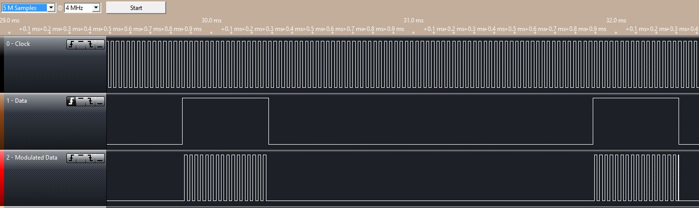
Modulated IR Signal Zoom View
As you can see, the modulated output is composed of a series of 38.4KHz clock pulses which are only generated when the digital signal should be high (logic 1). The remainder of the time the trace shows no output.
The final test is to see if this will trigger the camera, and yes, it still does.
Tags: Electronics, Software Development, STM8
Sunday, September 8th, 2013 at 11:57 am • Electronics, Software Development, STM8 • RSS 2.0 feed Both comments and pings are currently closed.
