Temperature and Humidity Sensor Module for the Netduino GO!
A while ago (forgive the pun), Arron Chapman and I started to collaborate on building a temperature and humidity sensor based upon the DHT22 sensor. One of the original posts discussing the module can be found here in the Netduino forums. From the very start we agreed that both the hardware and software would be open source. This post will discuss the basic hardware requirements and the software required to create a Temperature and Humidity Module for the Netduino GO!.
This post has a software bias given the relatively simple nature of the hardware being developed. Here is a flavour of what was achieved:
The design work for this module is the combined effort of Arron Chapman of Variable Labs and myself.
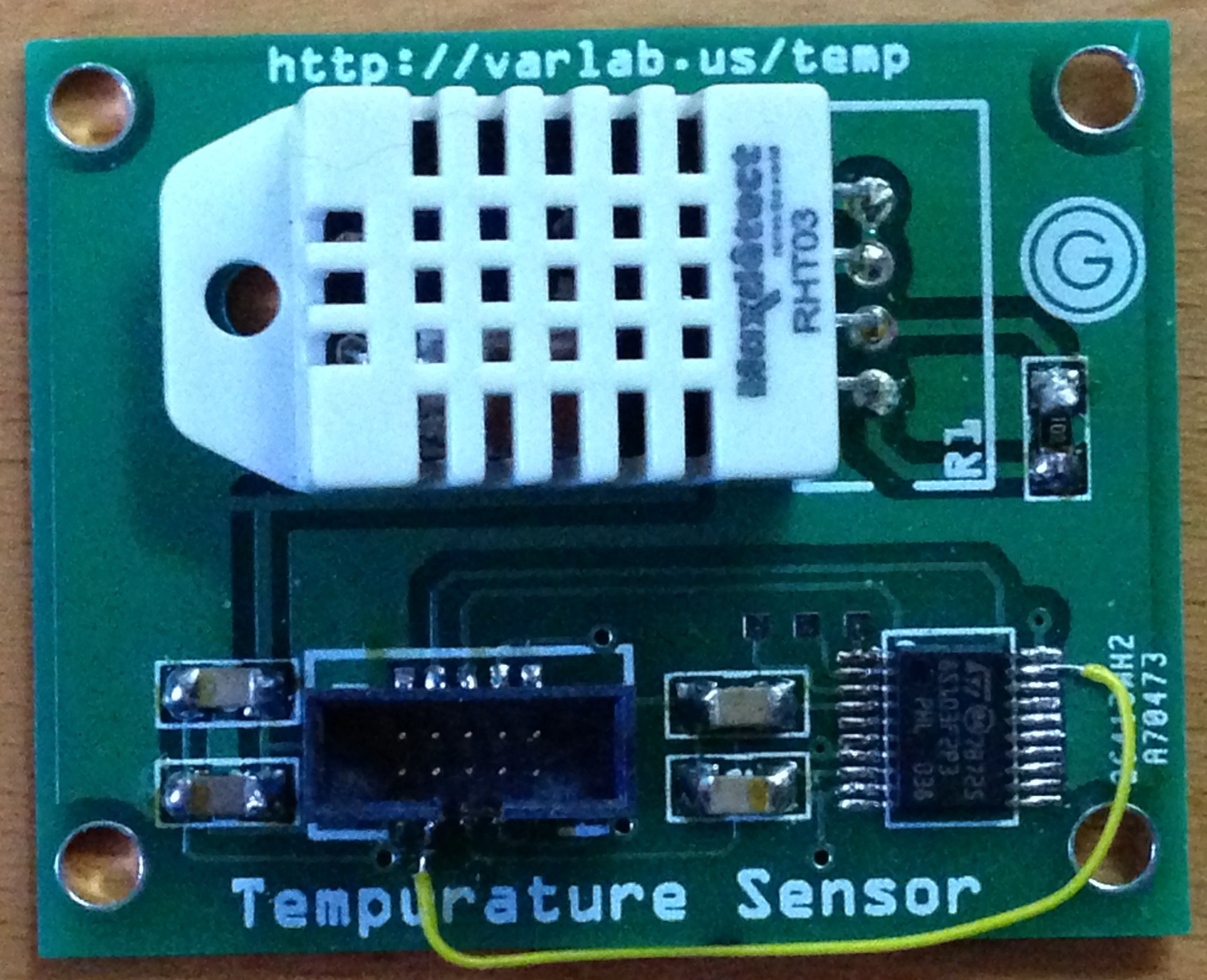
DHT22 Temperature and Humidity Sensor
The DHT22 is a four pin package capable of measuring temperature (+/- 0.5C) and humidity (+/- 5%). The package uses a single wire interface for communication and can be powered by 3.3-5V. The single wire protocol used is not compatible with Dallas single wire protocol.
The four pins should be connected as follows:
| Pin | Connection |
| 1 | VDD (3.3-5V) |
| 2 | Data/Signal |
| 3 | Ground |
| 4 | Ground |
Pin 2 (Data/Signal) should be connected to the microcontroller with a pull-up resistor to VDD.
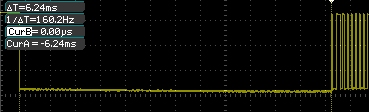
The microcontroller sends a start signal to the sensor which then responds with the data representing the temperature and humidity. The data is terminated with a check sum. The sensor can only be read at most once every 2 seconds. The trace for a full start, transmit and end signal looks like this:
The communication starts with the microcontroller sending the start signal. The microcontroller pulls the signal line low for at least 1-10ms. This ensures that the sensor can detect the microcontrollers signal. The microcontroller then pulls up the signal line and then waits for 20-40us for the sensor to respond.
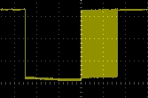
Zooming in on the start packet we would see something like:
As you can see, in this case the signal line was pulled low by the microcontroller for about 6.25mS.
The sensor then pulls the signal line low for 80us followed by pulling up the signal line for a further 80us. At this point the sensor is ready to start to transmit the temperature and humidity data.
The data is transmitted by varying the length of time the signal pin is held high. Transmission of a single bit starts by pulling the signal line low. A 0 bit is indicated by the sensor pulling the signal line high for 26-28us. pulling the signal high for 70us indicates a 1.
The temperature and humidity data is transmitted in a 40-bit packet. The first 16 bits hold the humidity information, the next 16 bits hold the temperature information and the final 8 bits contains the checksum. The following shows the full data packet from the sensor:
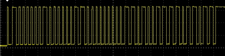
Both the temperature and the humidity are represented as an integer. The actual value is obtained by converting the binary number to decimal and then dividing by 10. If the high bit of the temperature reading is 1 then the value represents a negative temperature.
The final 8 bits of the data packet contain the checksum. The checksum is the result of adding the four bytes of the temperature and humidity data.
Schematic
Aside from the components required to make a basic module, the board really only required two parts, a single pull-up resistor and the DHT22 Temperature and Humidity sensor itself.
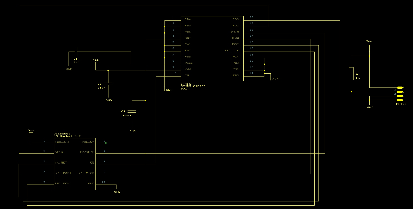
The components to the left of the diagram should be familiar if you have read the previous posts on making a module. The only additional parts can be seen to the right of the schematic.
Breadboard and PCB Prototypes
The original work for this module was completed on breadboard with an additional LM35 temperature sensor at the side of the DHT22. This second sensor was used as a reference to confirm the readings being generated by the DHT22. The simplicity of the design meant that moving to a PCB prototype was relatively simple and the iTeadStudio prototyping service made this affordable. A few weeks after ordering the prototype modules arrived:
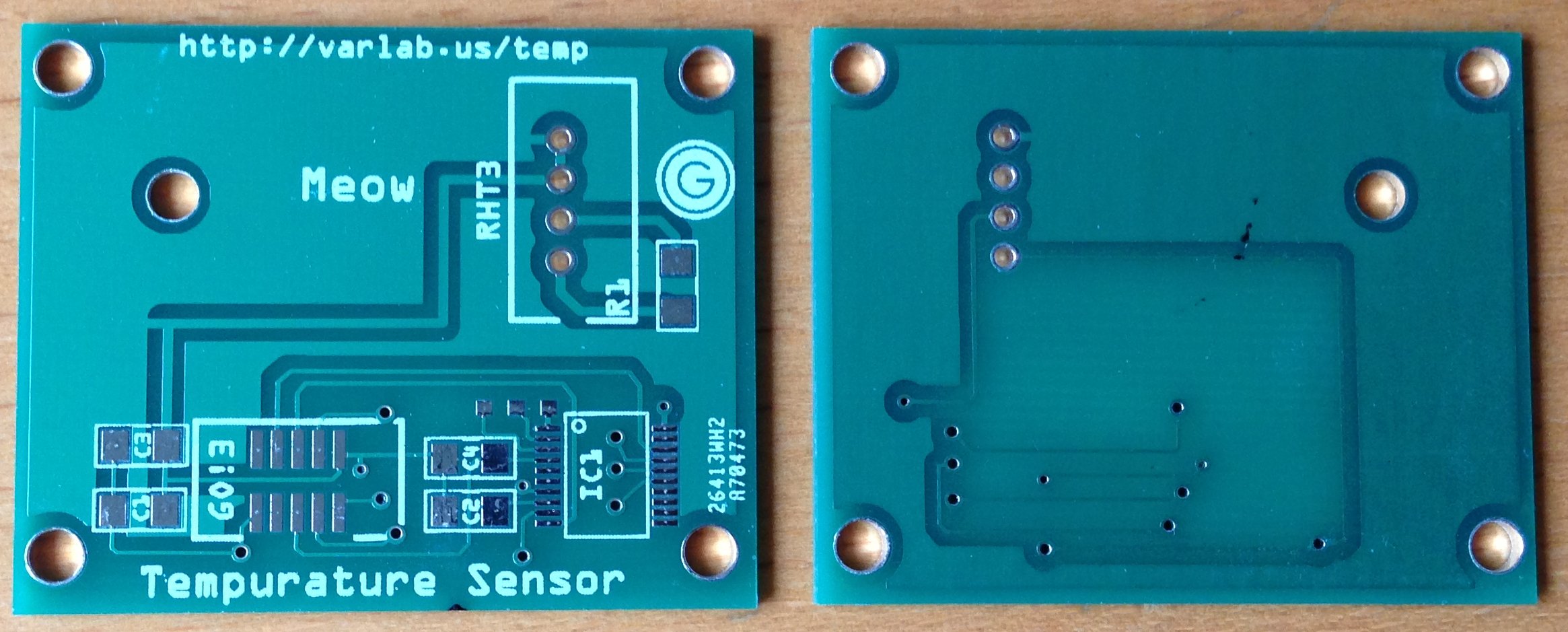
One of the tests I do on any PCBs I have made is a connectivity test. I do this when the board is unpopulated and simply walk through the list of connections and verify that there are no problems. I also take the software I have written during prototyping on the breadboard and check that the pins on the STM8S are connected to the correct points on the PCB. It was during this test that I found that a connection had been missed off of the original schematic, namely the connection from the GO! connector and the GPIO pin which is used to signal that data is ready for the GO! to consume. A quick fix once the board had been populated.
Notice the yellow wire – this goes to show the value of prototyping even for the smallest and seemingly simplest of projects.
Software
The one wire protocol means that the microcontroller will be both a master and a slave device as will the DHT22. We also have to allow for the fact that we also have the leave a 2 second gap between readings. The ideal way to implement this is to use a finite state machine. The cycle of events is as follows:
- Send the start signal and wait for 1-10ms
- Enter read mode and collect data
- Pause for at least 2 seconds
The state machine relies upon the timers to change the state based upon the minimum values for the time periods set by the sensor.
For the start signal, the signal line is set low and the timer started.
When the timer interrupt is triggered, the timer is turned off and reset. The signal pin is then switched from being an output pin to input with interrupts enabled. The timer is then restarted with a time period slightly larger than that required to ready all 40 bits of data from the sensor.
In the final stage, the interrupts are turned off, the data is processed and the system put to sleep (from a reading point of view) for more than 2 seconds.
In read mode, the system merely waits for interrupts to be generated by the sensor changing the state of the signal line. When an interrupt occurs, the time stamp (from the currently running timer) is read and recorded. The duration of the signal can then be calculated later (in stage three, pause mode) and the bit stream reconstructed from the timings.
Functionality
From a high level, the temperature and humidity module should provide the ability to read the current temperature and humidity (given the restrictions on the sensors delay of 2 seconds between readings). In addition, it would be desirable to allow the system to generate alarms for readings which are out of range.
As with all Netduino GO! modules, this functionality is split between the module and the module driver running on the Netduino GO!. The code on the module takes care of all the communication with the sensor. It takes this information and then responds to requests from the module driver on the Netdunio GO!.
STM8S Module
The software on the STM8S started life as the basic STM8S module software which has been used in previous posts.
The first modification needed is to add the state machine. The STM8S periodically reads the values from the sensor and store them for later retrieval by the Netduino GO! The regular nature of this update means that there is always a “current” reading available to the Netduiino GO! So the first thing we need is to setup a timer:
//--------------------------------------------------------------------------------
//
//  Setup Timer 2 to pause for 3.2 seconds following power up.
//
void SetupTimer2()
{
    TIM2_PSCR = 0x0a;       //  Prescaler = 1024
    TIM2_ARRH = 0xc3;       //  High byte of 50,000.
    TIM2_ARRL = 0x50;       //  Low byte of 50,000.
    TIM2_IER_UIE = 1;       //  Enable the update interrupts.
    TIM2_CR1_CEN = 1;
}
This initialisation code means that a reading is not available immediately. To go with this we will also need a variable to store the current mode along with some definitions:
//
//  Define the various modes for the state machine.
//
#define MODE_PAUSE                  0
#define MODE_SENDING_START_SIGNAL   1
#define MODE_READING_DATA           2
//
//  Current sensing mode.
//
int _mode = MODE_PAUSE;
Now for the critical part of the operation, we need to change to the correct state when the timer is triggered:
//--------------------------------------------------------------------------------
//
//  Timer 2 Overflow handler.
//
//  Note:   Normally we want the ISR to operate as quickly as possible but in
//          this case "as quickly as possible" just needs to be quick enough
//          for this sensor.  This means we have milliseconds for this ISR.
//
#pragma vector = TIM2_OVR_UIF_vector
__interrupt void TIM2_UPD_OVF_IRQHandler(void)
{
    TIM2_CR1_CEN = 0;
    switch (_mode)
    {
        case MODE_PAUSE:
            //
            //  Any pause has now completed, we need to start the
            //  read process.
            //
            PIN_DHT22_DATA = 0;
            TIM2_ARRH = 0xc3;       //  High byte of 50,000.
            TIM2_ARRL = 0x50;       //  Low byte of 50,000.
            TIM2_PSCR = 1;          //  Prescalar = 2 => count = 100,000 = 6.25mS
            TIM2_EGR_UG = 1;        //  Force counter update.
            _mode = MODE_SENDING_START_SIGNAL;
            break;
        case MODE_SENDING_START_SIGNAL:
            //
            //  At this point the start signal period has elapsed and we
            //  want to start to read data from the sensor.
            //
            PIN_DHT22_DATA = 1;
            PIN_DHT22_DIRECTION = 0;//  DHT22 pin is input.
            PIN_DHT22_MODE = 0;     //  DHT22 pin is floating input.
            EXTI_CR1_PDIS = 1;      //  Interrupt on rising edge.
            //
            //  We will get another interrupt after 5ms.  This should be
            //  enough time for the sensor to have generated the data and
            //  for us to process it.
            //
            TIM2_ARRH = 0x13;       //  High byte of 5,000.
            TIM2_ARRL = 0x88;       //  Low byte of 5,000.
            TIM2_PSCR = 4;          //  Prescalar = 4 => count = 5,000 (5 mS)
            TIM2_EGR_UG = 1;        //  Force counter update.
            _currentTiming = 0;
            _mode = MODE_READING_DATA;
            break;
        case MODE_READING_DATA:
            //
            //  At this point we should have read all of the data.  We
            //  now need to calculate the values and wait for 2 seconds
            //  before reading the next value.
            //
            PIN_DHT22_DATA = 1;     //  Set the output high after the data has been read.
            PIN_DHT22_DIRECTION = 1;//  DHT22 data pin is output.
            //
            //  We cannot read the sensor again for at least 2 seconds (32,800 with a prescalar
            //  of 11 should result in a ~4 seconds delay).
            //
            TIM2_ARRH = 0x80;
            TIM2_ARRL = 0x20;
            TIM2_PSCR = 0x0b;
            TIM2_EGR_UG = 1;        //  Force counter update.
            if (_currentTiming == 42)
            {
                DecodeData();
                if (_alarmsEnabled != 0)
                {
                    CheckAlarms();
                }
            }
            else
            {
                OutputStatusCode(SC_TOO_LITTLE_DATA);
            }
            _mode = MODE_PAUSE;
            break;
    }
    TIM2_CR1_CEN = 1;               //  Re-enable Timer 2.
    TIM2_SR1_UIF = 0;               //  Reset the interrupt otherwise it will fire again straight away.
}
Much of the code in the Interrupt Service Routine (ISR) above is concerned with recording the current state and resetting the timer ready to move into the next state. A key point to notice here is the change of use for the GPIO pin connected to the sensor.
When the ISR is entered and we are in pause mode (case MODE_PAUSE), we reset the timer and drop the signal line connected to the DHT22 (PIN_DHT22_DATA = 0). We then enter the next mode, MODE_SENDING_START_SIGNAL.
The next time the ISR is entered we should have just completed the time needed to keep the signal line low and for the sensor to be ready to send the data on the signal line. So we pull the signal line high and then change the direction of the GPIO line and the line becomes an input line which generates and interrupt. We then record the fact that we have changed to the next mode (MODE_READING_DATA), reset the timers and start to wait again.
In the final state, we should have received a full data packet from the sensor so we decode and process the data and then enter the pause mode once more. At this point the whole cycle repeats.
The state machine is now complete and we now need to start to look at recording the data. A little early experimentation showed that the sensor would generate 42 pulses. It was decided that the best way to record the pulses was to simply record the time at which they occurred. These timings could later be used to workout the pulse duration and hence if we had a 0 or 1. As we only needed the pulse duration then the actual time of the pulse was not needed, simply a reliable way of recording the duration. Timer 2 came to our aid. This timer was already running as it was required to control the state machine. We could simply record the value in this timer whenever an interrupt occurred. So starting with some definitions to support the storage of the data:
//
//  How many readings will we take?
//
#define MAX_READINGS                50
//
//  Somewhere to put the data.
//
int _sensorTimings[MAX_READINGS];
//
//  Which reading are we expecting next?
//
int _currentTiming = 0;
int _reading;
Next we need to capture the value in the timer when an interrupt occurred:
//--------------------------------------------------------------------------------
//
//  Process the interrupt generated by the DHT22.
//
#pragma vector = 8
__interrupt void EXTI_PORTD_IRQHandler(void)
{
    unsigned char high = TIM2_CNTRH;
    unsigned char low = TIM2_CNTRL;
    if (_currentTiming < MAX_READINGS)
    {
        _reading = (high << 8);
        _reading += low;
        _sensorTimings[_currentTiming++] = _reading;
    }
}
Now we have captured the data we need to decode the timings to obtain the temperature, humidity and the checksum. This method is called from the Timer 2 ISR above.
//--------------------------------------------------------------------------------
//
//  Decode the temperature and humidity data.
//
void DecodeData()
{
    unsigned short multiplier;
    //
    //  Extract the humidity.
    //
    unsigned short humidity = 0;
    multiplier = 32768;
    for (int index = 2; index < 18; index++)
    {
        if ((_sensorTimings[index] - _sensorTimings[index - 1]) > LOGIC_BOUNDARY)
        {
            humidity += multiplier;
        }
        multiplier >>= 1;
    }
    //
    //  Extract the temperature.
    //
    unsigned short temperature = 0;
    multiplier = 32768;
    for (int index = 18; index < 34; index++)
    {
        if ((_sensorTimings[index] - _sensorTimings[index - 1]) > LOGIC_BOUNDARY)
        {
            temperature += multiplier;
        }
        multiplier >>= 1;
    }
    //
    //  Extract the checksum.
    //
    unsigned short checksum = 0;
    multiplier = 128;
    for (int index = 34; index < 42; index++)
    {
        if ((_sensorTimings[index] - _sensorTimings[index - 1]) > LOGIC_BOUNDARY)
        {
            checksum += multiplier;
        }
        multiplier >>= 1;
    }
    //
    //  If the checksum is OK then overwrite the data.
    //
    unsigned short calcChecksum = 0;
    calcChecksum += humidity & 0xff;
    calcChecksum += ((humidity >> 8) & 0xff);
    calcChecksum += temperature & 0xff;
    calcChecksum += ((temperature >> 8) & 0xff);
    if ((calcChecksum & 0xff) == checksum)
    {
        _lastTemperature = temperature;
        _lastHumidity = humidity;
        _lastChecksum = checksum;
        OutputStatusCode(SC_OK);
        OutputDebugData(humidity, temperature, checksum);
    }
    else
    {
        OutputStatusCode(SC_CHECKSUM_ERROR);
    }
}
The LOGIC_BOUNDARY definition is simply the number of clock pulses which separates the 0 and the 1. A little empirical research gave this value as 100 clock pulses. This is not exactly as defined in the data sheet but it does give a reasonable working value.
As with all GoBus 1.0 modules, the definition of the data within the data packets (with the exception of the first byte) is left to the implementation. For this module the packets will be formatted as follows:
- 0x80 – Mandatory first byte
- ACK or NACK
- Type of data in the packet (for an ACK packet)
- Data (for ACK)
The type of data in the packet allows the system to respond to requests for information and also raise alarms.
Responding to the requests for readings is simply a case of copying the last set of readings from the global variable and putting them into the packet. The module then raises an interrupt (via NotifyGOBoard()) to indicate to the Netduino GO! that there is some data ready for processing:
//--------------------------------------------------------------------------------
//
//  Copy the sensor readings into the _txBuffer.
//
void CopySensorReadingsToTxBuffer()
{
    _txBuffer[3] = ((_lastHumidity >> 8) & 0xff);
    _txBuffer[4] = (_lastHumidity & 0xff);
    _txBuffer[5] = ((_lastTemperature >> 8) & 0xff);
    _txBuffer[6] = (_lastTemperature & 0xff);
    _txBuffer[7] = _lastChecksum;
}

//--------------------------------------------------------------------------------
//
//  Notify the GO! main board that there is some data ready for collection.
//
void GetReadings()
{
    _txBuffer[0] = 0x80;
    _txBuffer[1] = DHT22_ACK;
    _txBuffer[2] = DHT22_GET_READINGS;
    CopySensorReadingsToTxBuffer();
    NotifyGOBoard();
}
One desirable feature mentioned earlier was the ability to set alarms and have the module signal to the Netduino GO! that an alarm has been raised. The alarm system allows the user to set an alarm for the following events:
- Low temperature
- High temperature
- Low humidity
- High humidity
Setting an alarm is a simple operation as it only requires that the module records the alarms which have been set and the values associated with the alarm:
//--------------------------------------------------------------------------------
//
//  Set the alarm thresholds for the temperature and humidity.
//
//  Note that the alarm uses "special" out of range values to indicate that a
//  specified limit is not required.
//
void SetAlarms()
{
    //
    //  Start by turning everything off.
    //
    _alarmsEnabled = 0;
    _lowerTemperatureAlarm = SENSOR_MIN_TEMPERATURE;
    _upperTemperatureAlarm = SENSOR_MAX_TEMPERATURE;
    _lowerHumidityAlarm = SENSOR_MIN_HUMIDITY;
    _upperHumidityAlarm = SENSOR_MAX_HUMIDITY;
    //
    //  Now work out what we are looking at.
    //
    if (_rxBuffer[2] & ALARM_LOW_TEMPERATURE)
    {
       _lowerTemperatureAlarm = (_rxBuffer[3] * 256) + _rxBuffer[4];
       if (_lowerTemperatureAlarm < SENSOR_MIN_TEMPERATURE)
       {
           _alarmsEnabled = 0;
           RaiseNAK();
           return;
       }
       _alarmsEnabled |= ALARM_LOW_TEMPERATURE;
    }
    if (_rxBuffer[2] & ALARM_HIGH_TEMPERATURE)
    {
        _upperTemperatureAlarm = (_rxBuffer[5] * 256) + _rxBuffer[6];
       if (_upperTemperatureAlarm > SENSOR_MAX_TEMPERATURE)
       {
           _alarmsEnabled = 0;
           RaiseNAK();
           return;
       }
        _alarmsEnabled |= ALARM_HIGH_TEMPERATURE;
    }
    if (_rxBuffer[2] & ALARM_LOW_HUMIDITY)
    {
       _lowerHumidityAlarm = (_rxBuffer[7] * 256) + _rxBuffer[8];
       if (_lowerHumidityAlarm < SENSOR_MIN_HUMIDITY)
       {
           _alarmsEnabled = 0;
           RaiseNAK();
           return;
       }
       _alarmsEnabled |= ALARM_LOW_HUMIDITY;
    }
    if (_rxBuffer[2] & ALARM_HIGH_HUMIDITY)
    {
        _upperHumidityAlarm = (_rxBuffer[9] * 256) + _rxBuffer[10];
       if (_upperHumidityAlarm > SENSOR_MAX_HUMIDITY)
       {
           _alarmsEnabled = 0;
           RaiseNAK();
           return;
       }
        _alarmsEnabled |= ALARM_HIGH_HUMIDITY;
    }
    //
    //  Tell the Go board which alarms have been enabled (as an acknowledgement).
    //
    _txBuffer[0] = 0x80;
    _txBuffer[1] = DHT22_ACK;
    _txBuffer[2] = DHT22_SET_ALARMS;
    _txBuffer[3] = _alarmsEnabled;
    NotifyGOBoard();
}
The actual process of raising the alarm is performed in the Timer 2 ISR when we have decoded the data. Remember this code:
DecodeData();
if (_alarmsEnabled != 0)
{
    CheckAlarms();
}
When checking the alarms the application will compare the values for all of the alarms and then raise a single interrupt back to the Netduino GO! if one or more alarms need to be raised. The data packet sent back to the Netduino GO! also contains the current sensor readings. This means that the Netduino GO! does not have to request the sensor data to find out which alarm has been raised.
//--------------------------------------------------------------------------------
//
//  Check to see if the temperature/humidity is outside of any ranges and raise
//  an alarm if needed.
//
void CheckAlarms()
{
    unsigned char alarm = 0;
    if ((_alarmsEnabled & ALARM_LOW_TEMPERATURE) && (_lastTemperature < _lowerTemperatureAlarm))
    {
        alarm |= ALARM_LOW_TEMPERATURE;
    }
    if ((_alarmsEnabled & ALARM_HIGH_TEMPERATURE) && (_lastTemperature > _upperTemperatureAlarm))
    {
        alarm |= ALARM_HIGH_TEMPERATURE;
    }
    if ((_alarmsEnabled & ALARM_LOW_HUMIDITY) && (_lastHumidity < _lowerHumidityAlarm))
    {
        alarm |= ALARM_LOW_HUMIDITY;
    }
    if ((_alarmsEnabled & ALARM_HIGH_HUMIDITY) && (_lastHumidity > _upperHumidityAlarm))
    {
        alarm |= ALARM_HIGH_HUMIDITY;
    }
    if (alarm != 0)
    {
        _txBuffer[0] = 0x80;
        _txBuffer[1] = DHT22_ACK;
        _txBuffer[2] = DHT22_ALARM;
        CopySensorReadingsToTxBuffer();
        _txBuffer[8] = alarm;
        NotifyGOBoard();
    }
}
At this point the majority of the STM8S code is complete.
Netduino GO!
As with the STM8S code, the Netduino GO! driver is based upon the code developed previously and used as the basis for the Output Expander module. Much of this should be familiar and so we will only be considering the methods and supporting structures which implement specific features in this module. The class diagram for our module driver looks like this:
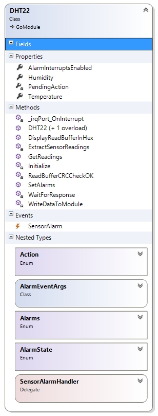
As you can see the module driver is not overly complex as it provides a few methods and supports a single interrupt.
The STM8S module returns temperature data on two occasions, the first is the explicit request by the Netduino GO! for the current readings, the second is when an alarm is raised. It therefore makes sense to abstract this code into a method:
/// <summary>
/// Extract the temperature and humidity data from the data which has been
/// generated by the STM8S.
/// </summary>
/// <param name="temperature">Temperature extracted from the buffer.</param>
/// <param name="humidity">Humidity extracted from the buffer.</param>
private void ExtractSensorReadings(out float temperature, out float humidity)
{
    //
    //  Verify the checksum before extracting the data.
    //
    int sum = 0;
    for (int index = 4; index < 8; index++)
    {
        sum += _readFrameBuffer[index];
    }
    if ((sum & 0xff) == _readFrameBuffer[8])
    {
        //
        //  Checksum good so extract the temperature and humidity data.
        //
        humidity = ((float) ((_readFrameBuffer[4] * 256) + _readFrameBuffer[5])) / 10;
        int sign = 1;
        byte highByte = _readFrameBuffer[6];
        if ((highByte & 0x80) == 0x80)
        {
            sign = -1;
            highByte &= (byte) 0x7f;
        }
        temperature = sign * ((float) ((highByte * 256) + _readFrameBuffer[7])) / 10;
    }
    else
    {
        throw new Exception("ExtractSensorData: Checksum error, discarding data.");
    }
}
The code which gets the current readings is relatively trivial:
/// <summary>
/// This method calls the AddOne method on the GO! module and then waits for the
/// module to indicate that there is a response ready.  The response is then read
/// from the module and the resulting value is returned to the caller.
/// </summary>
public void GetReadings()
{
    _writeFrameBuffer[0] = GO_BUS10_COMMAND_RESPONSE;
    _writeFrameBuffer[1] = (int) Action.GetReadings;
    WriteDataToModule();
    if (!WaitForResponse())
    {
        throw new Exception("GetReadings: Cannot communicate with the DHT22 module");
    }
}
Setting an alarm is also trivial, although the method is longer, with much of the work involving extracting the bytes of data and storing them in the transmit buffer:
/// <summary>
/// Set the alarms for the low/high temperature/humidity alarms.
/// </summary>
/// <remarks>
/// To turn an alarm off set the value to float.MinValue.
///
/// The alarms are triggered when the temperature/humidity goes below the low threshold
/// or above the high threshold.
/// </remarks>
/// <param name="lowTemperature">Low temperature alarm value.</param>
/// <param name="highTemperature">High temperature alarm value.</param>
/// <param name="lowHumidity">Low humidity alarm value.</param>
/// <param name="highHumidity">High humidity alarm value.</param>
public void SetAlarms(float lowTemperature, float highTemperature, float lowHumidity, float highHumidity)
{
    Alarms alarms = 0;

    if (lowTemperature != float.MinValue)
    {
        if ((lowTemperature < MIN_TEMPERATURE) || (lowTemperature > MAX_TEMPERATURE))
        {
            throw new ArgumentOutOfRangeException("SetAlarms: lowTemperature out of range.");
        }
        short lt = (short) (lowTemperature * 10);
        _writeFrameBuffer[3] = (byte) ((lt & 0xff00) >> 8);
        _writeFrameBuffer[4] = (byte) (lt & 0xff);
        alarms |= Alarms.LowTemperature;
    }
    if (highTemperature != float.MinValue)
    {
        if ((highTemperature > MAX_TEMPERATURE) || (highTemperature < MIN_TEMPERATURE))
        {
            throw new ArgumentOutOfRangeException("SetAlarms: highTemperature out of range.");
        }
        short ht = (short) (highTemperature * 10);
        _writeFrameBuffer[5] = (byte) ((ht & 0xff00) >> 8);
        _writeFrameBuffer[6] = (byte) (ht & 0xff);
        alarms |= Alarms.HighTemperature;
    }
    if (lowHumidity != float.MinValue)
    {
        if ((lowHumidity < MIN_HUMIDITY) || (lowHumidity > MAX_HUMIDITY))
        {
            throw new ArgumentOutOfRangeException("SetAlarms: lowHumidity out of range");
        }
        short lh = (short) (lowHumidity * 10);
        _writeFrameBuffer[7] = (byte) ((lh & 0xff00) >> 8);
        _writeFrameBuffer[8] = (byte) (lh & 0xff);
        alarms |= Alarms.LowHumidity;
    }
    if (highHumidity != float.MinValue)
    {
        if ((highHumidity < MIN_HUMIDITY) || (highHumidity > MAX_HUMIDITY))
        {
            throw new ArgumentOutOfRangeException("SetAlarms: highHumidity out of range");
        }
        short hh = (short) (highHumidity * 10);
        _writeFrameBuffer[9] = (byte) ((hh & 0xff00) >> 8);
        _writeFrameBuffer[10] = (byte) (hh & 0xff);
        alarms |= Alarms.HighHumidity;
    }
    _writeFrameBuffer[0] = GO_BUS10_COMMAND_RESPONSE;
    _writeFrameBuffer[1] = (int) Action.SetAlarms;
    _writeFrameBuffer[2] = (byte) alarms;
    WriteDataToModule();
    if (!WaitForResponse())
    {
        throw new Exception("SetAlarms: Cannot communicate with the DHT22 module");
    }
}
The really interesting work involves the receipt of data from the module. This is triggered by the interrupt being raised on the GPIO pin of the Netduino GO! connector.
/// <summary>
/// Handle the IRQ events generated by the GO! module.
/// </summary>
/// <remarks>
/// The module raises an interrupt when a command has been processed or when there
/// is data ready for the module.  The first task for this method is to retrieve
/// the buffer from the module and then work out what action should be taken.  The
/// module will have placed any relevant data into the write buffer prior to raising
/// the interrupt.
/// </remarks>
private void _irqPort_OnInterrupt(uint data1, uint data2, DateTime time)
{
    _writeFrameBuffer[0] = GO_BUS10_COMMAND_RESPONSE;
    _writeFrameBuffer[1] = (int) Action.GetBuffer;
    WriteDataToModule();
    if ((_readFrameBuffer[1] == GO_BUS10_COMMAND_RESPONSE) && (_readFrameBuffer[2] == DHT22_ACK) && ReadBufferCRCCheckOK())
    {
        float t, h;

        switch ((Action) _readFrameBuffer[3])
        {
            case Action.GetReadings:
                ExtractSensorReadings(out t, out h);
                Temperature = t;
                Humidity = h;
                _irqPortInterruptEvent.Set();
                break;
            case Action.SetAlarms:
                _irqPortInterruptEvent.Set();
                break;
            case Action.Alarm:
                if ((SensorAlarm != null) && (AlarmInterruptsEnabled == AlarmState.InterruptsEnabled))
                {
                    ExtractSensorReadings(out t, out h);
                    SensorAlarm(this, new AlarmEventArgs(t, h, (Alarms) _readFrameBuffer[9]));
                }
                break;
            default:
                throw new ArgumentException("Interrupt: Unknown action " + _readFrameBuffer[3].ToString());
                break;
        }
    }
}
This event allows the main program to set an alarm and then leave the module to work out when it needs to communicate with the Netduino GO!. This is achieved by the application setting the delegate SensorAlarm
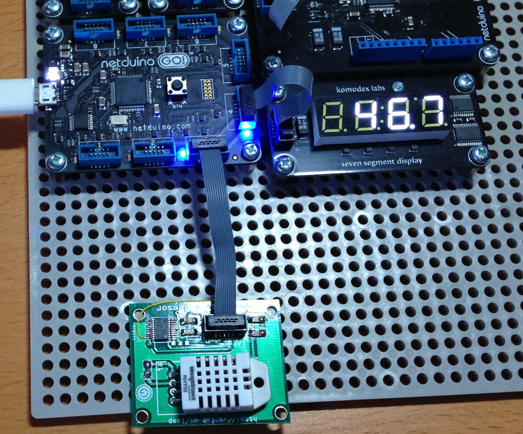
Testing
At this point we have the hardware and software complete. All that is needed now is to put the two together:
A quick test application (I promise, this will be last piece of the code in this article):
private static DHT22 module;

/// <summary>
/// Main program loop.
/// </summary>
public static void Main()
{
    SevenSegmentDisplay display = new SevenSegmentDisplay();
    display.SetBrightness(0.5F);
    display.SetValue("----");
    module = new DHT22();
    module.AlarmInterruptsEnabled = DHT22.AlarmState.InterruptsDisabled;
    module.SensorAlarm += new DHT22.SensorAlarmHandler(module_SensorAlarm);
    module.SetAlarms(35.0f, float.MinValue, float.MinValue, 10.0f);
    module.AlarmInterruptsEnabled = DHT22.AlarmState.InterruptsEnabled;
    Thread.Sleep(5000);
    int counter = 0;
    while (true)
    {
        try
        {
            module.GetReadings();
            Debug.Print("Reading: " + counter.ToString() + ", temperature: " + module.Temperature.ToString("f2") + "C, Humidity: " + module.Humidity.ToString("f2") + "%");
            string text = "Read  Temp  Hum " + (counter.ToString() + "    ").Substring(0, 5) + (module.Temperature.ToString("f1") + "C     ").Substring(0, 6) + (module.Humidity.ToString("f1") + "%     ").Substring(0, 5);
            display.SetValue(module.Temperature, 1);
            Thread.Sleep(2000);
            display.SetValue(module.Humidity, 1);
            Thread.Sleep(2000);
        }
        catch (Exception ex)
        {
            Debug.Print(ex.Message);
            display.SetValue("EEEE");
        }
        counter++;
        if (counter > 9999)
        {
            counter = 0;
        }
    }
}

/// <summary>
/// Catch the interrupt generated when one of the temperature/humidity (or both)
/// exceed the alarm values.
/// </summary>
private static void module_SensorAlarm(object sender, DHT22.AlarmEventArgs args)
{
    string message = "";
    if ((args.AlarmsRaised & DHT22.Alarms.HighHumidity) != 0)
    {
        message += "High humidity,";
    }
    if ((args.AlarmsRaised & DHT22.Alarms.HighTemperature) != 0)
    {
        message += "High Temperature,";
    }
    if ((args.AlarmsRaised & DHT22.Alarms.LowHumidity) != 0)
    {
        message += "Low Humidity, ";
    }
    if ((args.AlarmsRaised & DHT22.Alarms.LowTemperature) != 0)
    {
        message += "Low Temperature,";
    }
    message += " alarm raised: temperature = " + args.Temperature.ToString() + ", humidity = " + args.Humidity.ToString();
    Debug.Print(message);
}
The image above shows the DHT22 module connected to the Netduino GO!. A Komodex Labs Seven Segment Display is used to display the temperature and humidity.
And here is a video showing the module working. The system shows the temperature for a short while (16.8C) followed by the humidity (46.7%).
We were lucky last year as we had a particularly cold winter (lucky for testing). This allowed the module to be test outdoors in a reasonably cold environment. The sensor and the Netduino GO! performed as expected down to -10C when compared to an off the shelf digital thermometer and humidity unit. I would have waited for the temperature to drop further by my desire to prove the module has limits and I discovered that standing around outside with a coffee waiting for the module to read lower and lower temperatures had an interest threshold of about 10 minutes.
Conclusion
This module shows the power of combining microcontrollers to provide a combined system. The Netduino GO! would have found it difficult to have achieved the work completed by the STM8S. Similarly, the Netduino GO! provides the application developer with the simplicity and power of NETMF, something the STM8S could not achieve.
This module has yet to move from prototype into production. Maybe it will someday, just not today.
Tags: Electronics, Netduino, Software Development, STM8
Tuesday, June 25th, 2013 at 7:53 pm • Electronics, Netduino, Software Development, STM8 • RSS 2.0 feed Both comments and pings are currently closed.
