4 Digit, 7 Segment Display – Part 1 – Ouput a Byte
Update 18 March 2011: This is where this series of posts finishes for the minute as I appear to have fried the MAX7219 (or something else is wrong with the setup) as I can send commands to it but the output does not make any sense. I’ll have to return to this series when I have a new chip 🙁
This series of posts will discuss using the MAX7219 LED driver chip to drive a four digit, seven segment LED display. The series is made up of the following posts:
- Part 1 – Output a Byte (This Post)
Output a series of bytes from the Netduino Plus using the SPI protocol - Part 2 – Output an Unsigned Short
Similar to the first post but this time we will write a series of short integers using SPI. This will also start to implement the class which will write the data to the MAX7219 chip. - Part 3 – Displaying Numbers
Using the MAX7219 class to display a number on the display - Part 4 – Displaying Sensor Data
Hooking up a sensor to the Netduino and displaying the reading from the sensor.
Background Reading
The following posts provide some background information as these are similar projects:
Objective
The objective of these post is to connect the Netduino Plus to the breadboard and get a 5V logic signal representing a series of bytes. In order to do this it is necessary to convert the output from the Netduino Plus from 3.3V to 5V. I propose to experiment and use a 7408 quad 2 input AND gate to convert the 3.3V signal up to 5V. So for this post we will need the following components:
- Netduino Plus
- 1 x 74HCT08N quad 2 input AND gate
- Breadboard with 5V power supplied to the power rails
- Wire to connect the components
Theory
Part of this exercise is to see if we can convert a 3.3V signal into a 5V signal. This is necessary as the MAX7219 uses 5V inputs. The quad input AND gate was chosen to do this for no other reason than I had a few spare in the component box. The data sheet for this chip states that the minimum voltage for a high input is 3.15V when the chip is supplied with 4.5V. A quick experiment shows that a 3.3V input signal to this chip does indeed result in a high output.
So by connecting one of the inputs to the AND gate to 5V and the second to the signal source, then the output from the gate should reflect the input but translated from 3.3V to 5V.
One point to note is that the chip will take a little while for the signal on the inputs to be reflected on the output pins. This application will be running at a low frequency (10KHz) and so the chip should be able to keep up.
Software
The software is a simple starter program which cycles through the bytes from 0 to 255 and output’s these bytes on the SPI bus. The Saleae logic analyser is used to verify that the data is being output correctly. A small test program should demonstrate that the data is being transmitted on the bus correctly:
using System;
using System.Net;
using System.Net.Sockets;
using System.Threading;
using Microsoft.SPOT;
using Microsoft.SPOT.Hardware;
using SecretLabs.NETMF.Hardware;
using SecretLabs.NETMF.Hardware.NetduinoPlus;

namespace NetduinoPlusTestApplication
{
    public class Program
    {
        public static void Main()
        {
            SPI.Configuration config;
            SPI spi;
            byte[] b;

            config = new SPI.Configuration(Pins.GPIO_PIN_D10, false, 0, 0, false, false, 10, SPI.SPI_module.SPI1);
            spi = new SPI(config);
            b = new byte[1];

            while (true)
            {
                for (byte v = 0; v <= 255; v++)
                {
                    b[0] = v;
                    spi.Write(b);
                    Thread.Sleep(20);
                }
            }
        }
    }
}
Hardware
The following table shows how the Netduino Plus is connected to the 74HCT08N
| 74HCT08N | Connection |
| 2, 5, 10, 13, 14 | +5V |
| 7 | Ground |
| 12 | Netduino Plus digital pin 10 (used for CS) |
| 1 | Netduino Plus digital pin 11 (MOSI) |
| 4 | Netduino Plus digital pin 13 (Clock) |
The ground on the Netduino Plus should also be connected to the ground on the breadboard.
Results
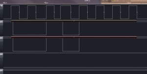
After completing the wiring the logic analyser was hooked up and the following trace appeared:
Scrolling through the trace show each of the ASCII characters being interpreted correctly.
So the next step it to start to build the class which will talk to the MAX7219.
Tags: Electronics, LED, Netduino
Tuesday, March 15th, 2011 at 1:09 pm • Electronics, Netduino • RSS 2.0 feed Both comments and pings are currently closed.

