Measuring Rain Fall
A new day and a new sensor to look at, the pluviometer.
The pluviometer is a mechanical sensor that looks a little like a see-saw. A small plastic bucket is placed on each side of the fulcrum. The buckets are designed so that when a critical mass of water is in one bucket it tips the see-saw and the bucket on the other side starts filling. The process continues as each bucket is filled and emptied. A picture paints a thousand words, so here is a view of the inside of the pluviometer:
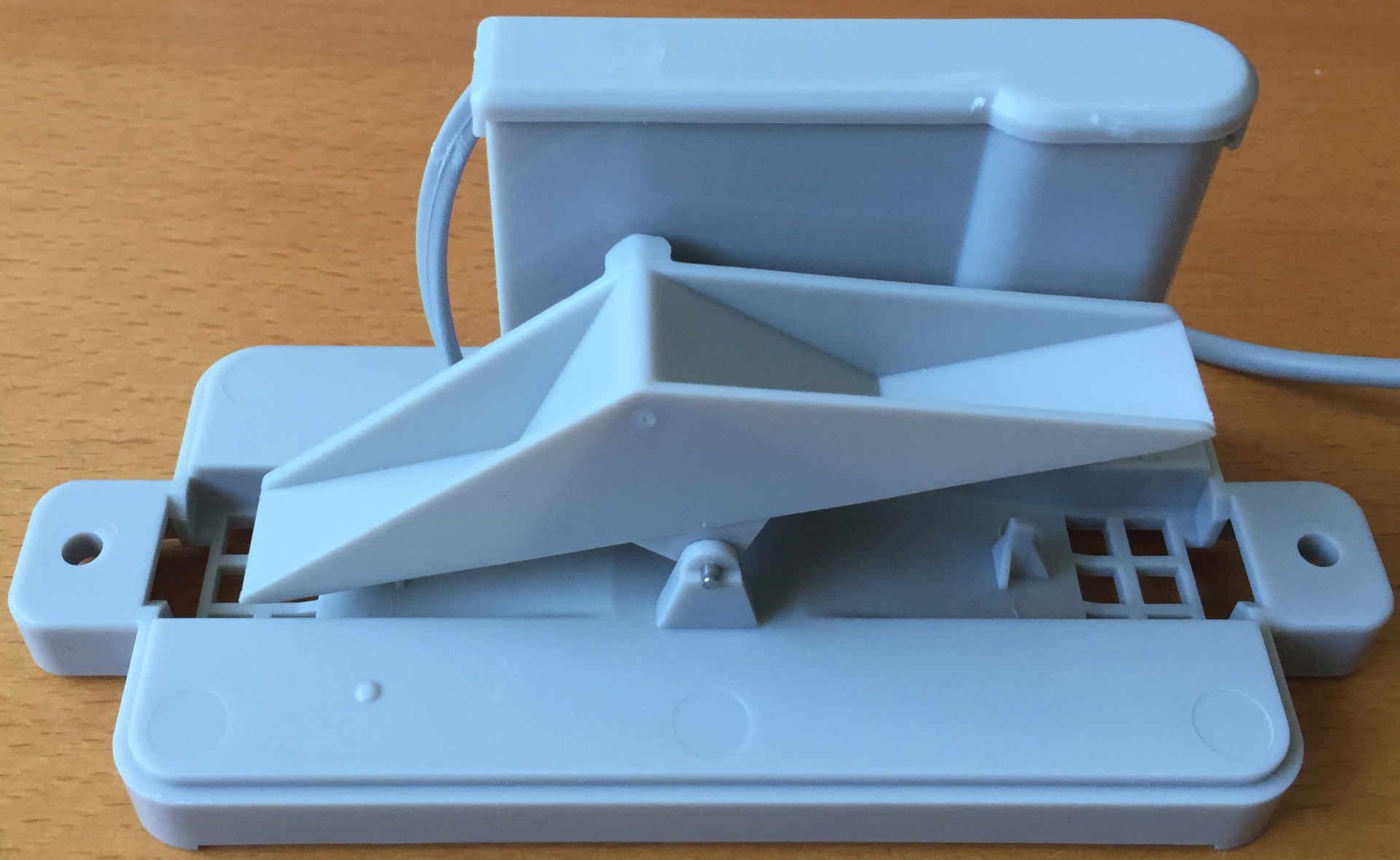
Inside the Pluviometer
A small magnet is placed on the see-saw and a reed switch is behind the fulcrum. The tipping motion triggers the reed switch each time the see-saw tips, this in turn generates a single pulse.
Reading the switch becomes a seeming simple repetition of the wind speed problem, namely debouncing a switch and attaching an interrupt.
One long term goal has to take this solution off grid. This will make power consumption a critical factor in the design. Attaching an interrupt does not necessarily become an attractive option as the Oak would be running continuously and with the WiFi running this would consume a fair amount of power.
According to the specification for the pluviometer, a pulse will be generated for every 0.2794mm of rainfall.
Offline Counting
One possible solution to the power problem would be to put the Oak to sleep and wake it up every say 5-15 minutes to take measurements and upload them to the cloud. Doing this would reduce power but would also mean that no measurements would be take during the sleep period if interrupts were used.
A cheap solution in terms of cost is to use the 74HC4040 counter. This could be put into a circuit and kept active while the Oak is sleeping. The output from the debounced switch would then be used as a clock signal for the 74HC4040. This would allow the pulses from the pluviometer to be counted while the Oak is sleeping.
The downside is that eight pins are needed to read the output from the counter. With only a small number of pins, many of which have already been used, this will require some way of adding extra pins to the system. Fortunately there are a number of digital IO expanders on the market. A common series of chips is the MCP23x17 chips. These add an additional 16 inputs/output pins with communication to the chip vis I2C (X=0) or SPI (X=S). The I2S variation will fit the bill nicely.One final connection that is required for the counter is a reset connection. Left to itself, the rain gauge counter would continue to count pulses until the counter overflowed and started from zero once more. From a design perspective there are a few options:
- Reset the counter each time it has been read
- Reset the counter once a day
- Let the counter overflow and detect the reset to zero
One consideration will be the amount of rainfall the system can detect before it resets to zero.
Maximum number of counts = 212
Which gives 4096 counts. However, for simplicity we will only consider the lower 8 bits, i.e. 0-255 counts. The system can always be expanded later should this be necessary (or if the system has the capacity).
Maximum rainfall = 255 * 0.2794 mm
Giving a maximum rainfall count of 71.247 mm per counting period. It is envisaged that the counting period would be somewhere in the region of 5-15 minutes. This would make an hourly average of 285mm assuming a steady rainfall and a 15-minute interval between counts.
This should be well within expectations for UK weather.
As an aside, the full 12-bits would allow for a rainfall of 1144mm per counting interval, or 4.5 metres of rain per hour.
Schematic
With a little supporting hardware to be added, the schematic looks as follows:
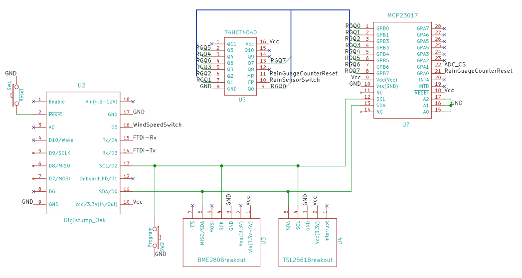
Weather Station Partial Schematic
Note that the BME280 and TSL2561 are also on the schematic.
The rain gauge counter bit values have been labeled RXQx, RG = Rain Gauge and Q is the standard notation for a bit in a logic design.
Software
The MCP23017 (I2C version of the IO expander) is sold by Adafruit. They have a standard Ardunio library for this component and so in the interest of code re-use, expediency and idleness this will be used.
So the first thing to do is to create an instance of the MCP23017 IO expander:
Adafruit_MCP23017 _outputExpander; // MCP23017, I2C controlled 16-port output.
Next up, the output expander needs to be setup. Looking at the schematic, the output from the counter is mapped to port B on the MCP23017. This maps to IO pins 8 to 15 inclusive. These bits should be set to inputs. One final piece of configuration is the reset pin, this needs to be set to output:
//
//  Set up the pluviometer, zero the counts and then attached and initialise the
//  counter to the output expander.
//
void WeatherSensors::SetupRainfallSensor()
{
    _pluviometerPulseCount = 0;
    _pluviometerPulseCountToday = 0;
    //
    //  Attach the rainfall counter to the output expander.
    //
    int index;
    for (index = 8; index < 16; index++)
    {
        _outputExpander.pinMode(index, INPUT);
    }
    //
    //  Attach the counter reset pin to the output expander and reset the counter.
    //
    _outputExpander.pinMode(PIN_RAINFALL_RESET, OUTPUT);
    ResetPluviometerPulseCounter();
}
As well as setting up the pulse counter, the above code resets internal counters for rainfall today and also resets the pulse count.
Reading the pulse counter is a simple matter to reading the state of each bit starting at 0:
//
//  Read the counter from the Rainfall sensor then reset the count.
//
void WeatherSensors::ReadRainfallSensor()
{
    byte mask = 1;

    _pluviometerPulseCount = 0;
    for (int index = 8; index < 15; index++)
    {
        if (_outputExpander.digitalRead(index) == 1)
        {
            _pluviometerPulseCount |= mask;
        }
        mask <<= 1;
    }
    _pluviometerPulseCountToday += _pluviometerPulseCount;
    ResetPluviometerPulseCounter();
}
Accuracy
The eagle-eyed amongst you will have spotted a small flaw in the above logic, namely that the pulse counter could increment whilst the system is reading the values. It turns out that this matters a great deal in some cases. Consider the following:
The pulse counter has counter 15 pulses (0b00001111). The software is processing these bit values and has processed bit 2, counter value = 7. A pulse is registered by the counter and the pulse count becomes 16 (0b00010000). The system processes bit 3 and finds it is 0 and then moves on to bit 4 and finds this is 1, i.e. 16. The counter then becomes 16 + 7 = 23 instead of 15. A little bit difficult to see, so lets put this in tabular form:
| Bit | Value | Decimal Value | Cumulative Sum | Counter |
| 0 | 1 | 1 | 1 | 00001111 |
| 1 | 1 | 2 | 3 | 00001111 |
| 2 | 1 | 4 | 7 | 00001111 |
| Counter increments here | 00010000 | |||
| 3 | 0 | 0 | 7 | 00010000 |
| 4 | 1 | 16 | 23 | 00010000 |
| 5 | 0 | 0 | 23 | 00010000 |
| 6 | 0 | 0 | 23 | 00010000 |
| 7 | 0 | 0 | 23 | 00010000 |
The counter column contains the value in the 74HC4040 counter chip (lower 8 bits only).
The problem occurs because the reading of the pulses is not instantaneous, the software takes longer to process the data than the counter takes to register a clock pulse and update the counter.
There are two possible solutions to this, both left for later investigation:
- Add an AND gate between the incoming rain gauge pulse and the 74HC4040 clock pin. This can be turned off when taking a reading.
- Check the documentation for the MCP23017 to see if the values can be latched and then read. Latching the values means that they cannot be changed; once latched and the values being read would be consistent.
Both offer a solution to the problem and will be left as a later refinement.
Conclusion
The pluviometer is a seemingly simple switch but it needs to run constantly. This presents a challenge when considering the requirement to save power where possible. This article presented a possible solution using a small number of components bringing powered on permanently.
The solution does introduce a possible error in the reading, although this should be reasonably small. A full analysis will be presented in a future article.
Tags: Electronics, ESP8266, Software Development
Monday, May 9th, 2016 at 6:02 am • Electronics, ESP8266, Software Development • RSS 2.0 feed Both comments and pings are currently closed.

[…] previous post looked at measuring rainfall using a pluviometer that generated a pulse for every 0.2794mm of rainfall. The conclusion of that […]