Why Do We Prototype?
I’ve been playing with the TLC5940 for a few years now. I aim to eventually have it play a part in a larger project but I need to get a few things ironed out first. I’m currently on my second prototype board, well they are more proof of concept boards really.
This post is not really about the boards themselves but more about the mistakes I’ve made along the way. Hence the title of this post, Why do we prototype?
I think the simple answer is that we make mistakes.
Design Goals
The long term aim of this project is to use the TLC5940 to drive a grid of LEDs. The chip allows the connection of the LEDs directly to the chip but I want to use a transistor (or an equivalent) to turn the LEDs on and off and not the TLC5940 directly.
Breadboard
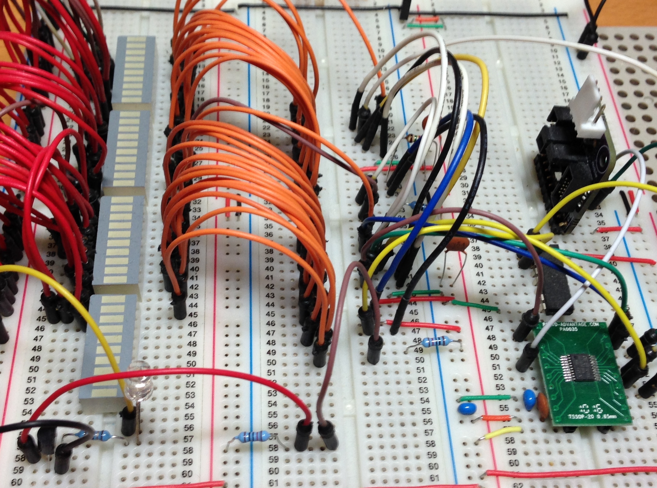
The breadboard circuit had all of the necessary components on the board and was pretty simple to get going. I started by connecting the LEDs directly to the TLC5940 and then built the software to run the circuit. The software runs on the STM8S103F3.
The next step is to connect one or more LEDs through a transistor. For this I used a PNP transistor and connected one of the LEDs using the transistor as a switch.
So far, so good. All is well with the world and I have some flashing LEDs.
The board (without the TLC5940s) looks like this:
Next step, prototype.
TLC5940 – Rev A
At this point I had designed a few boards and thought I’d push my SMD skills a little. I decided to use iTeads 5cm x 5cm manufacturing service and with the exception of the external connectors I would use SMD components only.
To give you an idea of the scale of this, the circuit requires 2 ICs plus 6 supporting discrete components. Each LED (and there are 16 of them) requires three discrete components for the driver plus the LED itself.
That is a pretty dense board for a beginner. Here is the 3D render of the board:
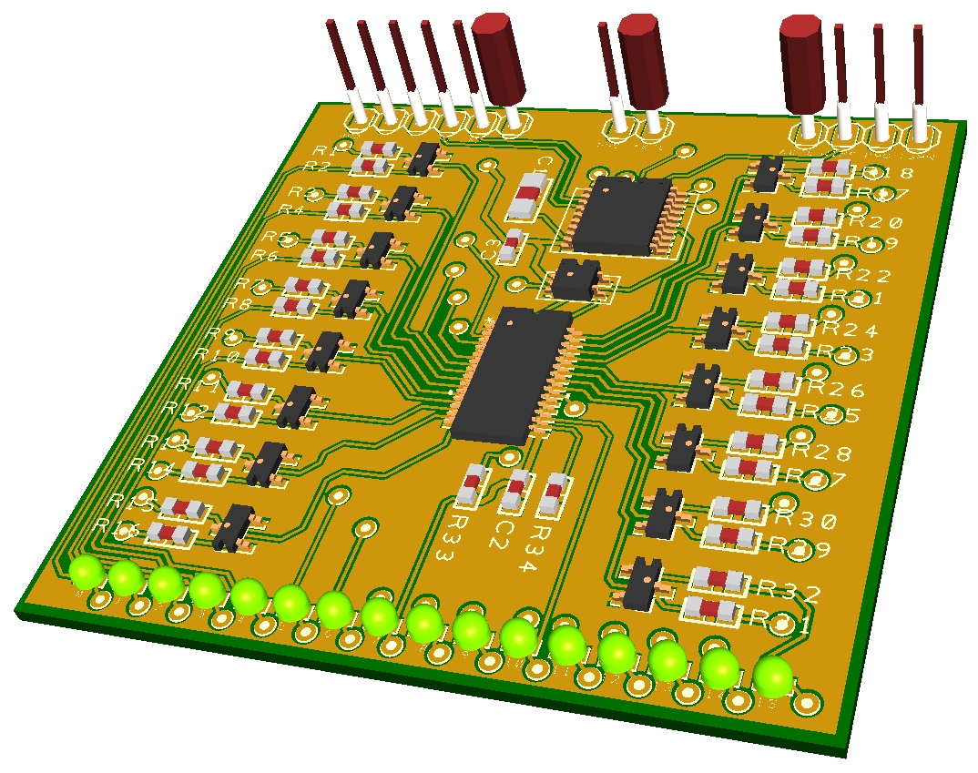
TLC5940 Rev A Prototype 3D Render
And the bare board itself:
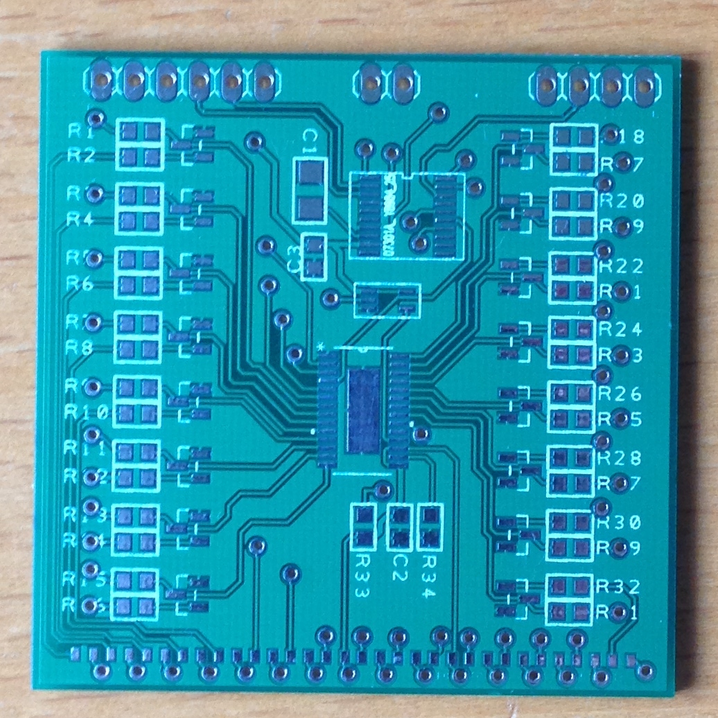
TLC5940 Driver Board Rev A – Front
and the back:
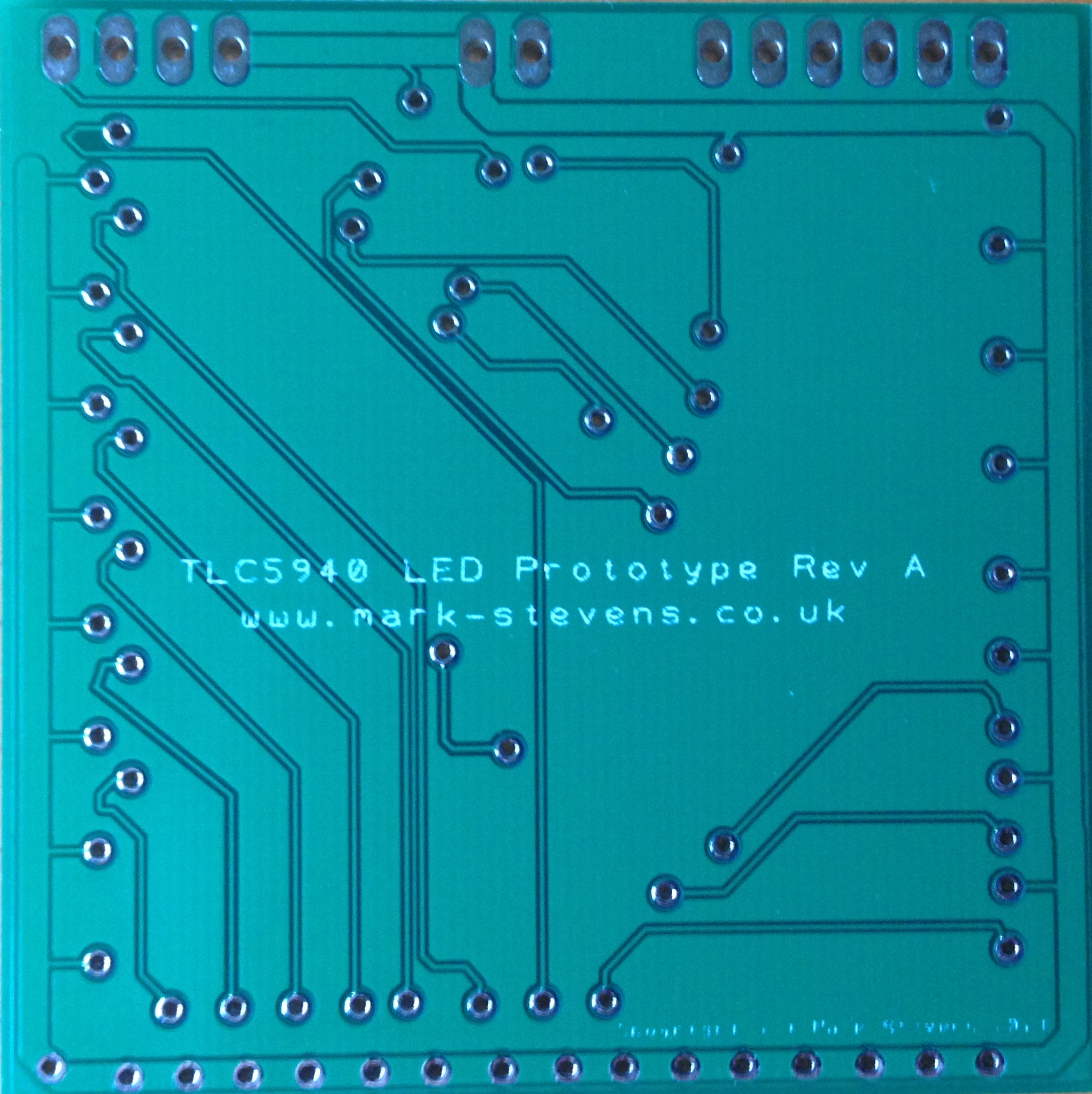
TLC5940 Driver Board Rev A – Back
Lesson 1 – Track Routing
I’ve been using DesignSpark PCB for all of my designs and it’s a pretty good piece of software and I am very impressed. One feature I have only recently used in anger is the ability to turn off some of the layers. Have a look at the traces to the left of the board below:
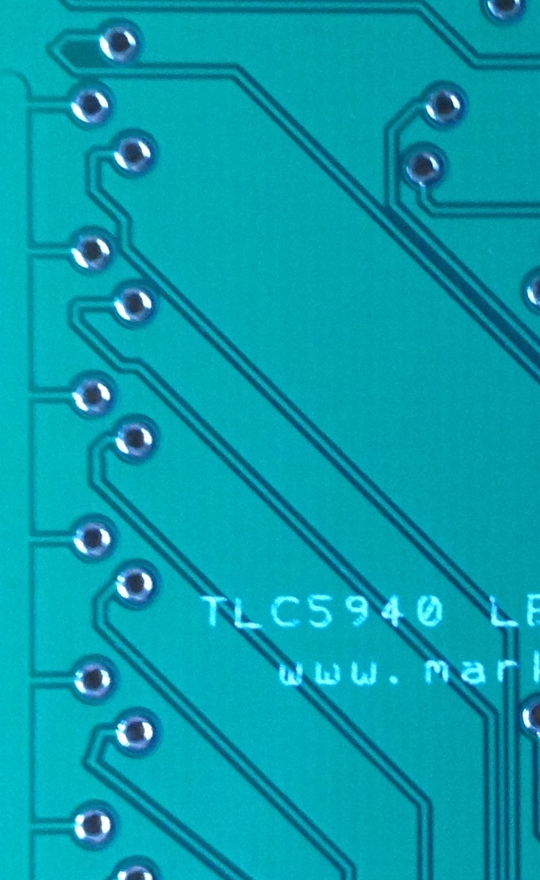
TLC5940 Prototype Rev A Routed Traces
This did not really cause an issue as there was no routing error but I could have routed these tracks more elegantly. The problem was caused by me having both the top and bottom traces visible at the same time. In my mind I had to route these tracks around the traces on the top layer as well as the artefacts on the bottom layer. Hence I took the traces around the via when I could have taken them directly from the via on the right (as viewed from below).
I would have spotted this more logical routing had I turned off the top copper view as soon as the trace passed through to the bottom copper layer.
Not really an error, more of a cosmetic nicety.
Lesson 2 – Use the Same Parts
Between the breadboard stage and the PCB stage I changed the part used in the driver. Not really too much of an issue except…
I did not get an equivalent PTH part and test it on the breadboard first.
As it stands the transistor driver circuit does not function and needs some more attention.
To enable testing of the remainder of the circuit you can use the following work around. Abandon the driver and change the value of the IREF resistor to allow a small enough current through the LED.
Lesson 3 – 0603 Parts Are Small Enough For the Hobbyist
Some of the parts I used in the design are 0402. These are small parts and really difficult to solder. It is especially difficult to see markings on the components.
In future I think 0603 is as small as I’ll go.
TLC5940 – Rev B
The Rev A board was a bit of a disaster. I never really managed to get the board working so it was time to go back to first principles and build a simpler board. Enter Revision B.
Revision B of the board will have a reduced brief. This board will use a mixture of SMD and PTH components. The STM8S and supporting components will be surface mount but the TLC5940’s will be PTH. I’m getting reasonably confident that I can get the STM8S on a board and working even in surface mount format.
Boards ordered, arrived and assembled. Here’s is a photo of it working:
Lesson 3 – Vcc and Ground Are Not Interchangeable
In redesigning the circuit I had to replace the TLC5940 component and so added the new one and changed the resistor value for the LEDs I’d be working with. Except I connected the IREF resistor to Vcc instead of ground.
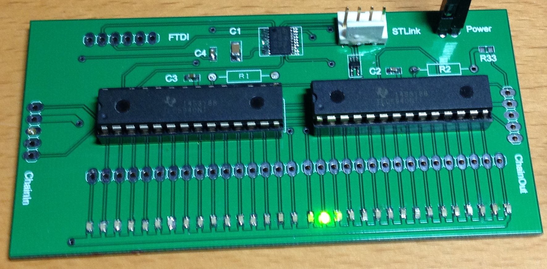
TLC5940 Prototype Rev B Working
Notice that the places for R1 and R2 are empty. That’s because they are on the bottom of the board:
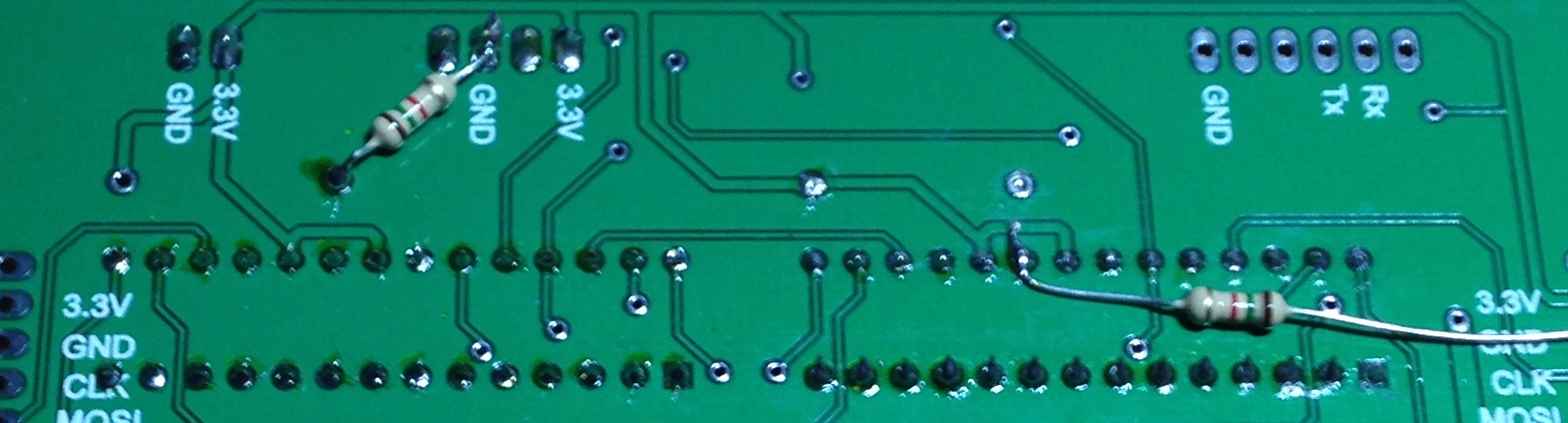
TLC5940 Prototype Rev B Resistors
Lesson 4 – Plastic Melts At Low Temperatures
For this circuit I use a single AND gate to square off the CCO output from the STM8S. This small IC was placed onto the board after the connector for the ST-Link programmer. The only problem was that I was using a hot air rework station to fix this part to the board. The hot air from the rework station caused some bubbling on the plastic of the connector.
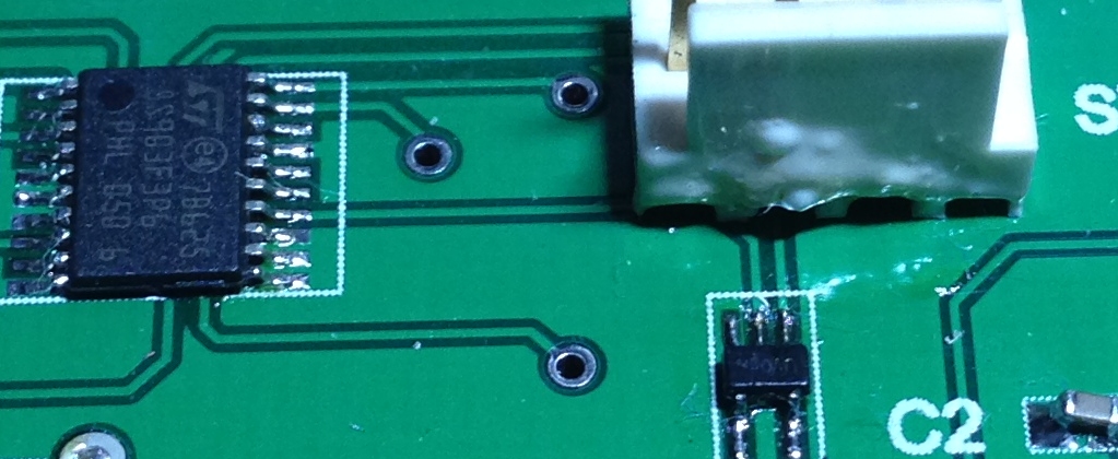
ST-Link Connector
I suppose this brings me to the next lesson.
Lesson 5 – Use the Board Luke
OK, so there’s been too much Star Wars on TV over Christmas.
What I really mean is, when prototyping, use all of the board available to you. The manufacturing process I used allowed for a 10cm x 5cm board (or anything up to that size) for a fixed price. For this board there is a lot of spare real estate and I could, with ease, have put that connector and the IC where they would not have interfered with each other.
The final board may have to be compact and fit into a location determined by the rest of the project but when testing you might as well use all of the space to your advantage.
Conclusion
I have a working Revision B board which mean I can free up the breadboard for other work but there is still some way to go before I have the final project completed. As with all things in life, this is a learning experience.
Hope you found this useful.
Tags: Electronics, LED, STM8
Wednesday, January 1st, 2014 at 10:58 am • Electronics, STM8 • RSS 2.0 feed Both comments and pings are currently closed.