STM32F4 Clocks
The STM32 contains several clocks each of which can be turned on or off when not used. In this post we will examine the clocks available and how they can be configured. To do this we will modify the simple GPIO example to change the clock parameters. Any changes to the system clock speed will increase or decrease the period of the delay. The results can be seen using an oscilloscope. We will look at the following topics:
At the end of this post you should be able to configure the system clock and introduce a known delay subject to the tolerances of the system clocks.
Clock Sources
The STM32 Reference Manual (RM0090) states that there are five clocks available:
- High Speed Internal (HSI) oscillator
- High Speed External (HSE) oscillator
- Phase Locked Loop (PLL)
- Low Speed Internal (LSI) clock
- Low Speed External (LSE) clock
As already noted, each clock can be turned on/off as required. Turning an unused clock off reduces the power consumption of the microcontroller.
The first three clocks are used to drive the system clock for the microcontroller. The final two are low speed clocks and are primarily used to drive the watchdogs.
HSI
After reset, the STM32 enables the HSI oscillator. This has a relatively low accuracy, only 1%, but is suitable for most applications. Using the HSI oscillator eliminates the need for an external clock in the final circuit design. On the STM32F4, the HSI oscillator has a clock speed of 16 MHz.
HSE
The STM32 can operate using an external clock circuit. It is possible to design an external clock to run with a greater accuracy than the internal HSI clock enabling finer control of the operating parameters of the final circuit. The exact specification of the external clock frequency varies but is typically 4-16 MHz.
The STM32F4 Discovery Board has a built in external oscillator circuit fitted with a 8 MHz crystal.
PLL
The PLL is used to multiply it’s input clock source by a factor varying between 2 to 16. The input of the PLL is one of HSI, HSE or HSE/2.
It is important to note that the configuration of the PLL cannot be changed once it has been enabled.
LSI
The LSI is a low power clock used for the watchdog timers.
LSE
The LSE is powered by an external 32.768 KHz clock. This provides a method of providing a low speed accurate clock for the real time clock.
System and Peripheral Clocks
Once the clock source has been selected it is necessary to configure the internal system and peripheral clocks. The internal clocks are:
- System Clock
- Advanced High Performance Bus (AHB)
- Low speed Advanced Peripheral Bus (APB1)
- High speed Advanced Peripheral Bus (APB2)
Each of these clocks can be scaled using prescalers. A fuller picture of the types of clocks and their relationships can be found in the STM32 Reference Manual (RM0090).
System Clock
The system clock is used to determine the speed at which instructions are executed and has a maximum speed of 168MHz.
Advanced High Performance Bus (AHB)
Derived from the system clock, this bus has a maximum speed of 168MHz.
Low speed Advanced Peripheral Bus (APB1)
Derived from AHB, this bus has a maximum speed of 42MHz.
High speed Advanced Peripheral Bus (APB2)
Derived from AHB, this clock has a maximum frequency of 84MHz.
Non-System Clock Peripherals
A number of the peripheral clocks are not derived from the system clock but have their own independent source.
USB OTG FS, Random Number Generator and SDIO Clock
These clocks are all driven by an independent output of the PLL. The maximum speed for these peripherals is 48MHz.
I2S
The I2S peripherals have their own internal clock (PLLI2S). Alternatively, this can be derived by an independent external clock source.
USB OTG HS and Ethernet Clock
These clocks are derived from an external source.
Microcontroller Clock Output
The STM32 provides the ability to output up to two clocks to the external circuit using the Microcontroller Clock Output (MCO) pins. Both of the outputs can have a prescaler applied. This can be in the range 1 to 5 inclusive.
Microcontroller Clock Output 1 (MCO1) is output on pin PA8. MCO1 output can be one of HSI, LSE, HSE or PLL scaled appropriately.
Microcontroller Clock Output 2 (MCO2) is output on pin PC9. MCO2 output can be one of HSE, PLL, System Clock or PLLI2S scaled appropriately.
The clock output is configured by selecting the appropriate alternative function for the GPIO port and is restricted to 100MHz.
Configuring the Clock
The number of features on the STM32F4 analysis and discussion of the registers and their function large. Luckily ST have come to the rescue and provided a configuration tool to help.
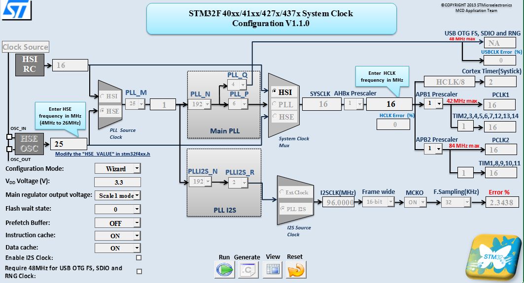
ST Clock Configuration Tool in Wizard Mode
This Excel spreadsheet can be run in both Expert and Wizard mode making it suitable for a wide range of users.
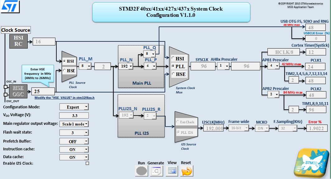
ST Clock Configuration Tool in Expert Mode
The grey number in the above illustration have been calculated whilst the numbers in black can be changed by the users.
The output from this spreadsheet is a source file (system_stm32f4xx.c) which can be added to your project. This file, system_stm32f4xx.c, contains three methods which can be called to setup the clocks on the microcontroller:
- SystemInit – Setup the system including the clocks
- SystemCoreClockUpdate – Setup the SystemCoreClock variable (clock frequency)
- SetSysClock – Setup the system clock (called from SystemInit)
We can see the effect of calling SystemInit by using the code from the simple GPIO example to the following:
#include "stm32f4xx_rcc.h"
#include "stm32f4xx_gpio.h"
#include "system_stm32f4xx.h"

int main()
{
    //
    //  Uncomment this line to see the effect of
    //  the clock change.
    //
	//SystemInit();
    //
    //  Initialise the peripheral clock.
    //
    RCC->AHB1ENR |= RCC_AHB1Periph_GPIOD;
    //
    //  Initialise the GPIO port.
    //
    GPIOD->MODER |= GPIO_Mode_OUT;
    GPIOD->OSPEEDR |= GPIO_Speed_100MHz;
    GPIOD->OTYPER |= GPIO_OType_PP;
    GPIOD->PUPDR |= GPIO_PuPd_NOPULL;
    //
    //  Toggle Port D, pin 0 indefinitely.
    //
    while (1)
    {
        GPIOD->BSRRL = GPIO_Pin_0;
        GPIOD->BSRRH = GPIO_Pin_0;
    }
}
If we run the code above with the SystemInit line commented out and hook an oscilloscope up to pin 0 of port D we get a square wave output with a frequency of about 1.5MHz.
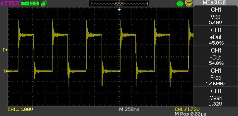
STM32F4 Output (1.46MHz)
Now uncomment the SystemInit line of code and re-run the example. This time we see that the output signal has a frequency of nearly 4.9MHz.
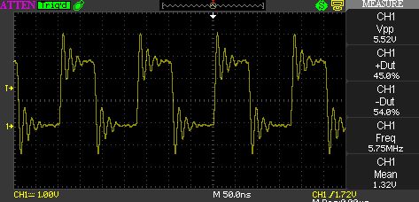
STM32F4 Output (5.75MHz)
Turning the configuration tool into expert mode and tweaking a few of the parameters allows the frequency of the output signal to go to 8.77MHz.
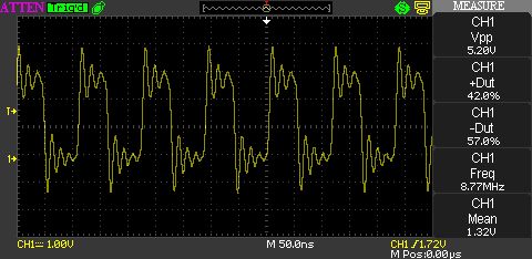
STM32F4 Output (8.77MHz)
Timings are based upon the optimisation level being set to no optimisation. Turning the optimisation on to the maximum speed allows an output signal of nearly 20MHz to be generated.
Conclusion
The STM32 contains a variety of clock sources and configuration using the registers within the microcontroller would be a complex task. The Clock Configuration tool eases the configuration of the internal and peripheral clocks generating the source code for system_stm32f4xx.c automatically.
The Clock Configuration tool and the associated guide can be downloaded from ST’s web site. The tool and document are in the following files:
- stsm-stm32091 Clock Configuration Tool
- AN3988 Clock Configuration Tool User Guide
Tags: Electronics, Software Development, STM32, The Way of the Register
Thursday, March 28th, 2013 at 10:53 am • Electronics, Software Development, STM32 • RSS 2.0 feed Both comments and pings are currently closed.