Connecting up the STM8S003
A few days ago I wrote about my first attempt at coding for the STM8S003 but forgot to mention how I connected up the chip to the PC. So here is a quick post explaining how to do it.
The STM8S Chip
The STM8S chip chosen was the STM8S003F3 in a TSSOP20 package. This form factor is incredibly small and there is no way to mount it on a breadboard without some for of adapter. Luckily Sparkfun have a SSOP to DIP Adapter 20-Pin in their catalog. However, I could not get hold of one in the UK so I ended up getting the 28 pin version instead. A bit of a waste but it worked.
So armed with the adapter, a chip and some connectors it was time to break out the soldering iron. A brief experiment with drag soldering did not work and I finally settled on soldering each pin very carefully with the finest soldering iron tip I had.
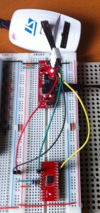
The next job was to mount all of this on the breadboard. There are only really two additional components required for this circuit, 1uF and 0.1uf ceramic capacitors. You can see both of these to the left of the chip in the above picture. The 0.1uf capacitor connects ground and +3.3V and acts as a power smoothing capacitor. The 1uF capacitor connects Vcap and ground.
ST-Link/V2 Programmer and Debugger
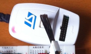
The chip is programmed using the low cost (£20 approx) ST-Link/V2 programmer and debugger. This works with both the STM8 and STM32 range of processors.
Putting it all Together
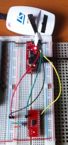
If we put the two components together we get something which looks like this:
The red PCB between the programmer and the STM8S circuit is a breadboard power supply which has been set to supply 3.3C to the circuit. The wires connecting the STM8 to the programmer are as follows:
| Colour | Description |
| Red | Power (3.3V) |
| Black | Ground |
| Green | Reset |
| Yellow | Data |
Tags: Electronics, Software Development, STM8
Sunday, April 29th, 2012 at 6:56 am • Electronics, STM8 • RSS 2.0 feed Both comments and pings are currently closed.


