The Controller Board
Having a cube of LEDs is of little use without a controller board. As previously mentioned, all 512 LEDs can be controlled from just 7 lines from the Netduino Mini. As you will have seen during the testing, we can turn on any LED by connecting the anode to a positive supply and the entire layer in which it sits to ground.
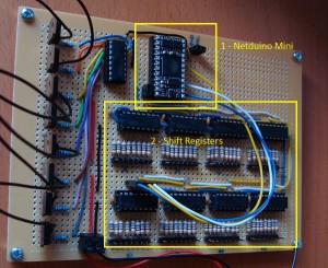
The positive supply is a relatively simple thing to achieve and our good friend the 74HC595 shift register will help us there. Connecting to ground requires a little more work but this is achieved using the 74HC238 and a bank of transistors. At the end of this process I had the following board:
So, a quick walk around the board. Box one contains the Netduino Mini. The two connectors to the bottom left of the board allow the Mini to be connected to the computer – they are the Mini’s COM1 connections. The two connectors at the top right are for the ground and the 5V from my USB – FTDI connector. Only ground is connected, the other connector allows me to stop the 5V lead from flying around and touching something it shouldn’t.
Box 2 contains the bank of 8 x 74HC595s, current limiting resistors and a connector to allow a ribbon cable to be connected the cube to the controller. These will determine which of the LEDs received power. Each of the shift registers will control one row of LEDs, 8 rows need 8 registers. So the shift registers can control 64 LEDs at once.
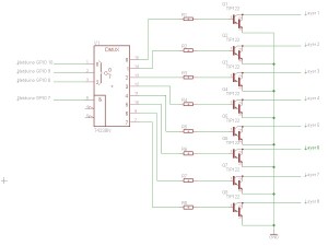
The remainder of the electronics on the board determine which layer will be connected to ground. The 74HC238 takes four lines from the Mini. Three of the lines represent a binary number 0-7, the fourth line is an output enable line. The decoder takes the number and switches on one of one of the output lines. This is in turn connected to the base of a TIP122 transistor. Applying power to the base allows the layer the transistor is connected to connect to ground.
So all is in place to use persistence of vision to be used to give the appearance that the cube is permanently switched on. Starting with the cube switched off we load the shift registers with the data for layer 0. We then load the 74HC238 with 0 and enable the output. This will turn on the transistor for layer 0 which will allow current to flow through the LEDs in layer 0. We then turn the cube off by disabling the output of the 74HC238 and repeat for layer 1 and so on.
Shift Registers
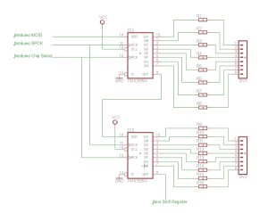
A little more repetition – don’t you just love it. The eight shift registers are wired together in a cascade with the shifted output of one register forming the input of the next. By connecting eight together we can control 64 outputs.
The basic connections for the shift registers is as follows:
This needs to be repeated until all eight of the registers are connected as in the above diagram. In the controller board diagram the serial data in wires are blue, the clock wires are white and the enable wires are yellow.
Note that a 100nF ceramic capacitor is connected between power and ground and one is placed by each IC as close to the IC as possible.
The current limiting resistors for this project were selected to keep the current per LED at 25mA per LED. The nearest value actually puts this at 26mA per LED. Multiplying this up means that a layer when all of the LEDs are switched on will draw 1.6A. The maximum output current rating per pin on the 74HC494 is 35mA so we are getting close to the limit per pin.
Layer Switching
Layer switching is achieved by connecting a layer to ground through a TIP122 transistor. This should be capable of sinking 2A which is greater than the 1.6A which we could theoretically need to sink if all of the LEDs on a layer are switched on. The 74HC238 selects which layer is connected to ground – or in fact none of them may be connected if the output from the 74HC238 is disabled. The circuit diagram for this part of the controller looks as follows:
Again, a 100nF capacitor is placed across power and ground for this IC.
Connecting the Controller to the Cube
The collector for each of the TIP122’s should be connected to a different layer. I connected mine with layer zero being the top layer.
Each of the shift registers should be connected to one row of LEDs. I connected mine with bit zero at the right of the cube. This was done with one of the female connectors (to fit the male connector on the controller board) and some ribbon cable.
The result of these two wiring decisions was a rather odd co-ordinate system. You may decide to use something more conventional.
Adding the Netduino Mini
The Netduino Mini connections have already been noted on the above schematics.
Tags: Electronics, LED, Netduino
Sunday, March 18th, 2012 at 5:10 pm • Electronics, Netduino • RSS 2.0 feed Both comments and pings are currently closed.


