Cheap Yellow Display SPI
Sunday, March 16th, 2025

Cheap Yellow Displays look to be an ideal way of experimenting with the ESP32 ecosystem. They are small, simple and are equipped with a number of built in sensors / modules. They sounded ideal for a project to monitor a test environment, displaying data and sending detailed logs over a WiFi network.
Early tests went well with the various features prototyped and each feature working well. The problems started when the various components were brought together, at which point the SPI implementation on the board started to become an issue.
This post runs through the details of the problem and the hardware solution selected.
There are a number of variants of the Cheap Yellow Display and this post suggests a destructive hardware modification to the circuit board to resolve the issue. It is recommended that the schematic is double checked before proceeding with any modifications.
What Are Cheap Yellow Displays?
I first came across the Cheap Yellow Displays when they were mentioned in a Hackaday Post in early January. They are small boards, about the size of a credit card. The boards contain an array of devices including:
- Screen with touch sensor
- Ambient light
- RGB LED
- Audio amplifier
- SD Card slot
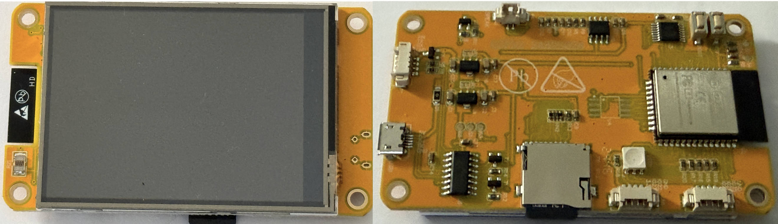
All of this is powered by an ESP32 with 4MB of flash and can be obtained for about £9 when purchased from China. Sounds perfect for a small project that will monitor UART traffic and log / send the data over the network.
There is also an open source repository containing code, schematics and a list of hacks for the board.
The board ordered was the ESP32-2432S028, time to break out VS Code and ESP-IDF.
One feature missing from this package was the ability to natively connect an ESP-PROG programmer to the board. This means that development will have to fall back to using ESP_LOGx or printf statements for debugging. No JTAG here.
Proof of Concept
As mentioned, the board is going to be used to connect to a 3.3V TTL UART and log the information, optionally sending the data to a server on the network. The device has a display with touch screen so this becomes an obvious choice to configure and monitor operation of the device.
The SD Card slot also means that data can be logged to a file for longer term storage and transfer to a host computer.
For the initial proof of concept we need to look at the following tasks:
- Use LVGL to create a user interface on the LCD screen
- Respond to touch events
- Access the SD card reader
The first two tasks we proven to work using the LVGL examples in the open source repository.
Access to the SD card was proven using the SD SPI example in the Espressif repository.
Combining the Examples
Next step was pulling the two pieces of work together, this is where things started to go wrong. Adding the SD Card example code to the LVGL code generated initialisation errors when spi_bus_initialize was called.
The code as written used the following interfaces:
- SPI2_HOST for LCD display
- SPI3_HOST fo the touch sensor
IDF exposes three SPI hosts, 1 – 3, so the logical step is to assign SPI1_HOST to the SD card interface. This is where the problems started to arise. Using the third SPI interface resulted in the following error:
E (296) spi: spi_bus_initialize(802): SPI bus already initialized
The issue can be distilled down to the following code:
void app_main(void)
{
    spi_bus_config_t buscfg_display = {};
    buscfg_display.mosi_io_num = (gpio_num_t) 13;
    buscfg_display.miso_io_num = (gpio_num_t) 12;
    buscfg_display.sclk_io_num = (gpio_num_t) 14;
    buscfg_display.quadwp_io_num = -1;
    buscfg_display.quadhd_io_num = -1;
    buscfg_display.max_transfer_sz = 4000;
    buscfg_display.flags = 0;
    buscfg_display.intr_flags = 0;

    ESP_ERROR_CHECK(spi_bus_initialize(SPI2_HOST, &buscfg_display, SPI_DMA_CH_AUTO));

    spi_bus_config_t buscfg_touch = {};
    buscfg_touch.mosi_io_num = GPIO_NUM_32;
    buscfg_touch.miso_io_num = GPIO_NUM_39;
    buscfg_touch.sclk_io_num = GPIO_NUM_33;
    buscfg_touch.quadwp_io_num = -1;
    buscfg_touch.quadhd_io_num = -1;
    buscfg_touch.data4_io_num = -1;
    buscfg_touch.data5_io_num = -1;
    buscfg_touch.data6_io_num = -1;
    buscfg_touch.data7_io_num = -1;
    buscfg_touch.max_transfer_sz = 4000;
    buscfg_touch.flags = SPICOMMON_BUSFLAG_SCLK | SPICOMMON_BUSFLAG_MISO | SPICOMMON_BUSFLAG_MOSI | SPICOMMON_BUSFLAG_MASTER | SPICOMMON_BUSFLAG_GPIO_PINS;
    buscfg_touch.isr_cpu_id = ESP_INTR_CPU_AFFINITY_AUTO;
    buscfg_touch.intr_flags = ESP_INTR_FLAG_LOWMED | ESP_INTR_FLAG_IRAM;

    ESP_ERROR_CHECK(spi_bus_initialize(SPI3_HOST, &buscfg_touch, SPI_DMA_CH_AUTO));

    spi_bus_config_t buscfg_sdcard = {};
    buscfg_sdcard.mosi_io_num = 23;
    buscfg_sdcard.miso_io_num = 19;
    buscfg_sdcard.sclk_io_num = 18;
    buscfg_sdcard.quadwp_io_num = -1;
    buscfg_sdcard.quadhd_io_num = -1;
    buscfg_sdcard.max_transfer_sz = 4000;

    ESP_ERROR_CHECK(spi_bus_initialize(SPI1_HOST, &buscfg_sdcard, SPI_DMA_CH_AUTO));
}
The traceback for the error is:
0x4008582b: _esp_error_check_failed at /Users/username/esp/esp-idf/components/esp_system/esp_err.c:49
0x400d6859: app_main at /Users/username/Public/spitest/main/spitest.c:49 (discriminator 1)
This highlights the line causing the error as:
ESP_ERROR_CHECK(spi_bus_initialize(SPI1_HOST, &buscfg_sdcard, SPI_DMA_CH_AUTO));
There are some notes in the IDF documentation about using SPI1 and possible issues that can be encountered.
The unanswered question is why do we need three SPI busses?
Brief Recap – SPI
Readers who are experienced with how SPI works can skip this section.
SPI has the concept of a central (master) device and a number of peripherals (slave) devices. The devices communicate using two or three lines with an optional device selection signal (chip select). The four lines are usually labelled as:
- COPI (MOSI) – data signals from the central controller to the peripherals
- CIPO (MISO) – data from the peripheral to the central device
- CLK (SCK) – clock signal generated by the central device
- CS – chip select, used to identify the peripheral being addressed.
The chip select signal is not always connected to a central device. Take for example, when there is only one SPI peripheral in a circuit. You do not always need the chip select signal, if the peripheral has a CS line then this could be connected to high or low depending upon the peripheral requirements. In this was the peripheral is always listening which is fine as this is the only device on the bus.
For a system with multiple SPI peripherals there are two options:
- Put each peripheral on its own bus
- Use the CS line to switch peripherals on / off
The first option means that for every peripheral we would need three signals, COPI, CIPO and CLK. The CS line could be hard wired as the bus is a single peripheral bus model. This design means that two devices would consume six pins from the microcontroller.
The second option is less costly as you use the same three data and clock pins (COPI, CIPO and CLK) for all of the peripherals. You need an additional CS pin for each peripheral but this still results in a saving in the pin count. So for the two peripheral example, you need the three data and clock pins along with a CS1 and CS2 line, so only 5 pins rather than 6.
A more detailed description of the history of SPI and other features of the bus including timing characteristics (modes) can be found on WikiPedia on the Serial Peripheral Interface page.
Cheap Yellow Display SPI Implementation
A quick look at the schematic for the Cheap Yellow Display shows how the three SPI devices have been connected to the ESP32. The pin out is as follows:
| Signal Name | LCD | Touch Sensor | SD Card |
|---|---|---|---|
| COPI (MOSI) | 13 | 32 | 23 |
| CIPO (MISO) | 12 | 39 | 19 |
| CLK | 14 | 25 | 18 |
| CS | 15 | 33 | 5 |
The use of three distinct sets of pins, one for each interface, means that we will need three SPI interfaces requiring investigation and resolution of the SPI1_HOST initialisation error.
Hardware Solution
Another option is to look at a hardware solution, moving one of the devices to another bus and using CS to determine the source and destination for the data. Control of the LCD and SD card are both under control of the application. The touch screen peripheral is reacting to the user input and the application has no control over when this will occur. The touch screen peripheral will therefore remain on one bus and the LCD and SD card will share a bus. The wiring becomes:
| Signal Name | LCD | Touch Sensor | SD Card |
|---|---|---|---|
| COPI (MOSI) | 13 | 32 | 13 |
| CIPO (MISO) | 12 | 39 | 12 |
| CLK | 14 | 25 | 14 |
| CS | 15 | 33 | 5 |
First task, disconnect the data and clock signals for the SD card leaving the CS pin connected. The image below shows the three tracks that need cutting (highlighted in red):

Next up, connect the SD card data and clock pins to the LCD SPI bus. The modified board looks something like this:

Software Modifications
The software modifications should be relatively trivial, a simple change to the MOSI, MISO and CLK pins used for the SD card. The CS pin assignment remains unchanged from the sample application.
Conclusion
Modifying the hardware has reduced the number of SPI host interfaces required bringing the interface count down to two. Early experience has shown that the system starts and runs as expected. The three peripherals, touch, LCD and SD card all respond as expected.
Back to providing UART monitoring functionality.

