NE555 Power on Reset
It is essential that when a computer (or any other electrical device) starts, that it starts in a known good state. For a computer, this is accomplished with a power on reset circuit. This circuit is responsible for holding the various reset signals in a known state for a defined period of time when power is applied. Some computers also utilise a reset switch to manually trigger this same reset process.
This post will look at a simple reset circuit from the 1980s using the NE555 timer.
Requirements
The circuit under consideration should perform the tasks:
- Provide two reset signals, one high (Reset) and one low (Reset).
- Hold the reset lines in a known state when power is applied.
- Provide a manual reset facility.
All of the above can be achieved using a modified monostable NE555 circuit.
Schematic
The modified schematic for the monostable circuit looks like this:
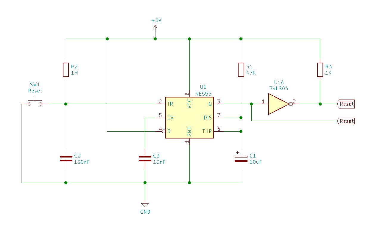
NE555 Reset Circuit Schematic
The basic theory of this circuit is that a low pulse on the trigger pin generates a single shot pulse on the output pin of the NE555.
The resistor and capacitor in the right-hand part of the circuit form a standard monostable configuration. This circuit is taken from the NE555 datasheet. Using the formula in the datasheet, the period of the stable, high pulse on the output is given by the formula:
Period = 1.1 * R * C
Using the values in the circuit, R = 47K and C = 10uF. Plugging these values into the equation we find that the period of the stable pulse is 0.517 seconds.
The inverter provided by the 74LS04 allows for the generation of both a high and a low (Reset and Reset) signals from the circuit.
The resistor and capacitor on the left hand side of the circuit debounce the switch connected to the trigger of the circuit. They also hold the trigger under the 1.67V threshold for a short period of time following startup. This provides the power on reset element of the circuit.
This circuit can also be viewed using the logical layout discussed in the previous aricle on the theory of operation:
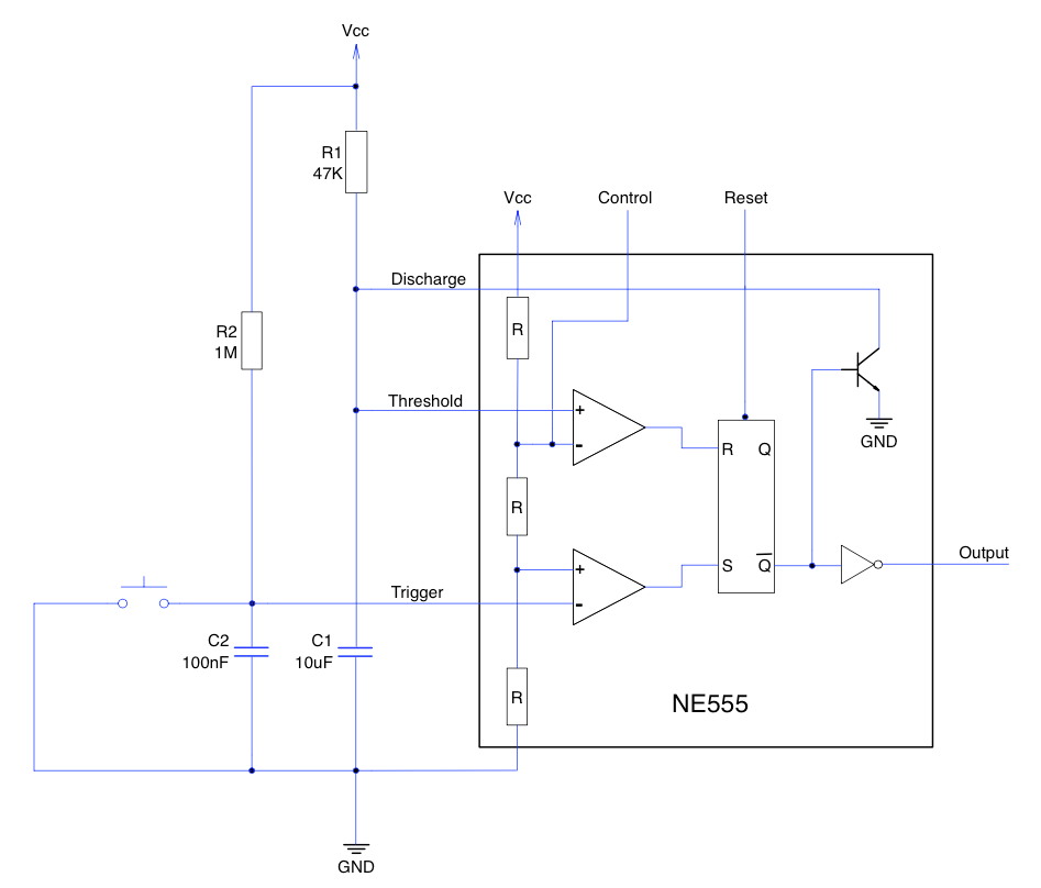
NE555 Logical Layout
Implementation
Putting the above circuit together on breadboard gives something like the following:
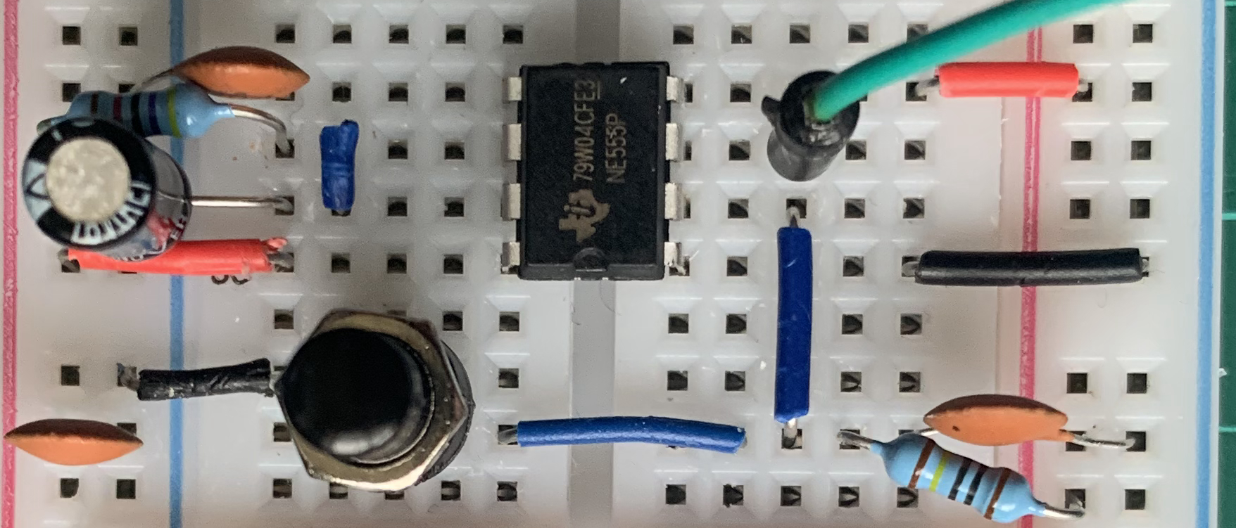
NE555 Reset Circuit on Breadboard
Observations
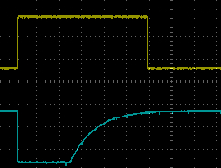
In the following, all images from the oscilloscope will show the NE555 output in yellow and where present, the signal on the trigger pin will be in blue.
At startup, it is expected that there should be a short (500ms approx) signal on the output pin of the NE555.
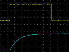
NE555 Power on Reset Oscilloscope Output
So far, so good. The next requirement is to allow the user to manually reset the system. This is done using the switch connected to the trigger pin on the NE555. Pressing the button shows the following on the oscilloscope:
NE555 Reset Circuit Short Button Press
The short press on the button generates the required reset pulse on the output pin of the NE555.
The datasheet for the NE555 warns against holding the trigger pin low for a period of time longer than the duration of the output pulse. So in this case, the trigger pin should not be held low for longer than 517ms. This could be a problem as it is easy to exceed this period in normal use. So what happens if the trigger pin is held low for an extended period of time? Changing the scale on the oscilloscope to 250ms per division and we see the following:
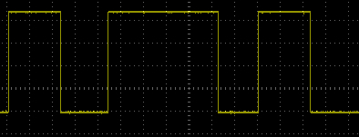
NE555 Reset Circuit Multiple Button Presses on Oscilloscope
The leftmost pulse is the result of a short press of the button. As expected, the output of the NE555 goes high for 517ms.
The middle pulse shows what happens when the button is pressed and held for an extended period of time. In this case, the button was pressed for about 2s. As you can see, the reset pulse remains high for the duration of the button press and then returns low.
The rightmost pulse shows what happens when the switch is pressed once more for a short period. As you can see, the NE555 returns to its normal mode of operation and generates a 517ms pulse.
Conclusion
The NE555 really does deserve it’s reputation as a versatile chip. This simple circuit provides a digital circuit with the ability to start in a known state by providing a reset pulse when power is applied to the system. It also provides a mechanism for resetting a system on demand using a switch connected to the trigger pin.
And now for a piece of history, circuits such as this appeared in many of the early 8-bit computers from the 1980s.
Tags: Electronics
Monday, January 20th, 2020 at 10:19 am • Electronics • RSS 2.0 feed Both comments and pings are currently closed.
