Making the D70 Remote More Permanent
Now that we have the major components of the Nikon D70 Remote Control unit in place it is about time the unit moved from breadboard to a more permanent home. The last day or two has seen the unit move from breadboard to protoboard.
The layout is nothing too complex and at this point I am not too worried about the physical dimensions of the board. So the task at hand is to convert the following schematic into a working board:
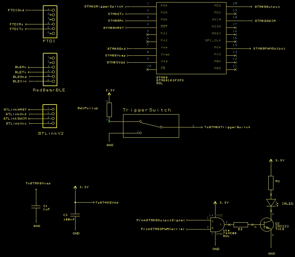
Nikon D70 Remote Control Schematic
There are plenty of resources out there discussing the techniques for putting together a prototype board from a schematic so we won’t cover these here. Only thing to do is dive in with some Photos starting with the top of the board with the IC’s in place:
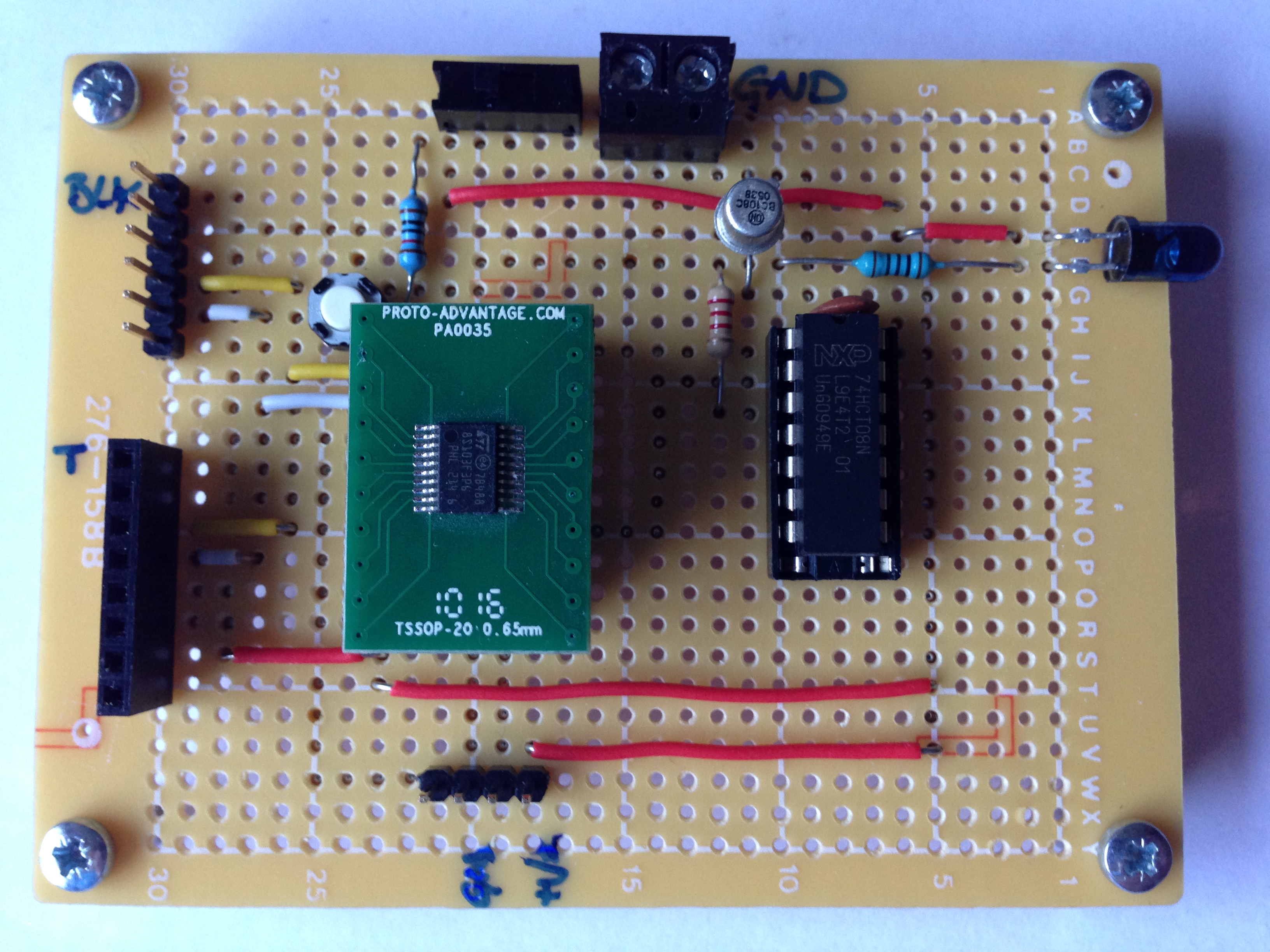
Nikon D70 Protoboard Upper
The eagle eyed amongst you may have noticed that I used a 16-pin DIP socket for the AND gates when I should really have used a 14-pin socket. A little solder soon fixed that problem.
The connectors on the right hand side of the board provide the serial connections by FTDI (upper male connector) and RedBear BLE Mini (lower female connector). The connection at the bottom of the board is the STLink/V2 connector.
And the bottom of the board:
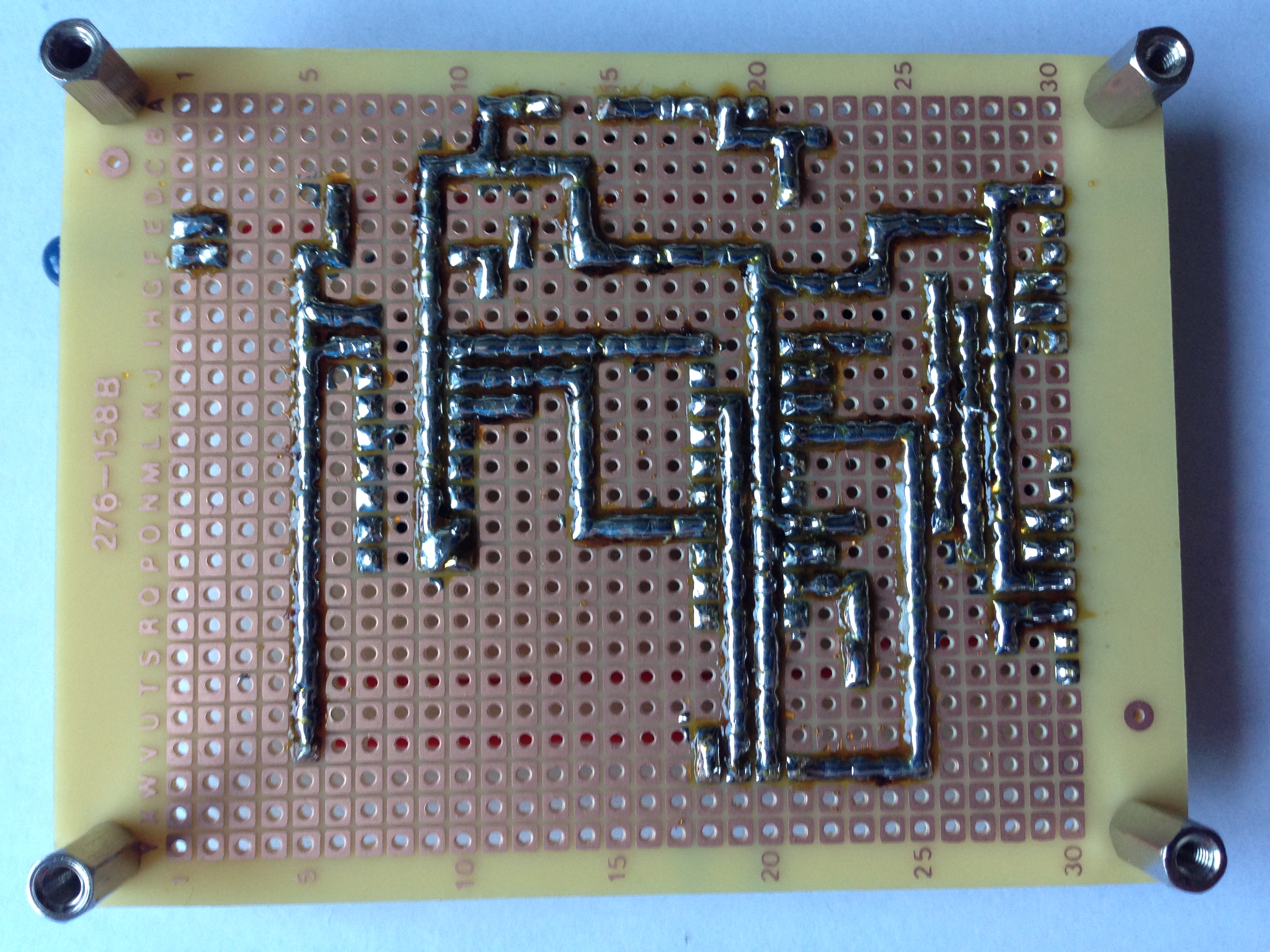
Nikon D70 Protoboard Lower
Conclusion
Building the board was not too difficult. The code for the STM8S needed a small modification to move the application from the STM8S105 on the Discovery board to the STM8S103F3 which I have on the DIP to protoboard converter.
Next steps:
- Allow the EEPROM to be reprogrammed by UART
- Add support for programmable intervals
- Consider making the unit standalone (selectable intervals, status display)
- iPhone application using the RedBear BLE Mini to control the unit
If all goes well it may even end up with a PCB being manufactured and a 3D printed case being made.
Forgot to mention, it still triggers the camera.

